Freelance Electronics Components Distributor
Closed Dec 25th-26th
800-300-1968
We Stock Hard to Find Parts

AT84AD001BITD

Part # AT84AD001BITD
Description ADC DUAL FLASH 1GSPS 8BIT PARALLEL 144LQFP - Trays
Category IC
Availability Out of Stock
Qty 0
Qty Price
1 + $154.41500


Technical Document


DISCLAIMER: The information provided herein is solely for informational purposes. Customers must be aware of the suitability of this product for their application, and consider that variable factors such as Manufacturer, Product Category, Date Codes, Pictures and Descriptions may differ from available inventory.

16
AT84AD001B
2153C–BDC–04/04
Figure 9. 1:1 DMUX Mode, Clock I = ADC I, Clock IN = ADC Q
Figure 10. 1:1 DMUX Mode, Decimation Mode Test (1:16 Factor)
Notes: 1. The maximum clock input frequency in decimation mode is 750 Msps.
2. Frequency(CLKOI) = Frequency(Data) = Frequency(CLKI)/16.
CLKI
CLKOI
(= CLKI/2)
VIN
TA
N
N + 1
N + 4
N + 6
Pipeline delay = 3.5 clock cycles
TDO
DOQA[0:7]
Address: D7 D6 D5 D4 D3 D2 D1 D0
0 X X X 0 X 0 0
DOIA[0:7]
DOIB[0:7] and DOQB[0:7] are high impedance
CLKOQ is high impedance
CLKIN
N + 2
N + 3
N + 5
N - 2
N - 6
N + 2
N - 4
N
N - 1
N - 5
N + 3
N - 3
N + 1
Pipeline delay = 3 clock cycles
TDO
VIN
N - 16
N
N + 16
N + 32
CLKI
16 clock cycles
CLKOI
DOIA[0:7]
N + 16 N + 32 N + 48
N - 16
N
DOQA[0:7]
N + 16 N + 32 N + 48
N - 16
N
Address: D7 D6 D5 D4 D3 D2 D1 D0
1 0 X X 0 X 0 0
DOIB[0:7] and DOQB[0:7] are high impedance
CLKOQ is high impedance
17
AT84AD001B
2153C–BDC–04/04
Figure 11. Data Ready Reset
Figure 12. Data Ready Reset 1:1 DMUX Mode
Note: The Data Ready Reset is taken into account only 2 ns after it is asserted. The output clock first completes its cycle (if the reset
occurs when it is high, it goes low only when its half cycle is complete; if the reset occurs when it is low, it remains low) and then
only, remains in reset state (frozen to a low level in 1:1 DMUX mode). The next falling edge of the input clock after reset makes
the output clock return to normal mode (after TDR).
DDRB
CLKI or
CLKQ
500 ps
ALLOWED
ALLOWED
FORBIDDENFORBIDDEN
1 ns min
500 ps
1 ns min
CLKI or
CLKQ
CLKOI or
CLKOQ
DOIA[0:7] or
DOQA[0:7]
VIN
TA
N
N
DDRB
2 ns
TDR
TDR
Pipeline Delay + TDO
Clock in
Reset
N + 1
18
AT84AD001B
2153C–BDC–04/04
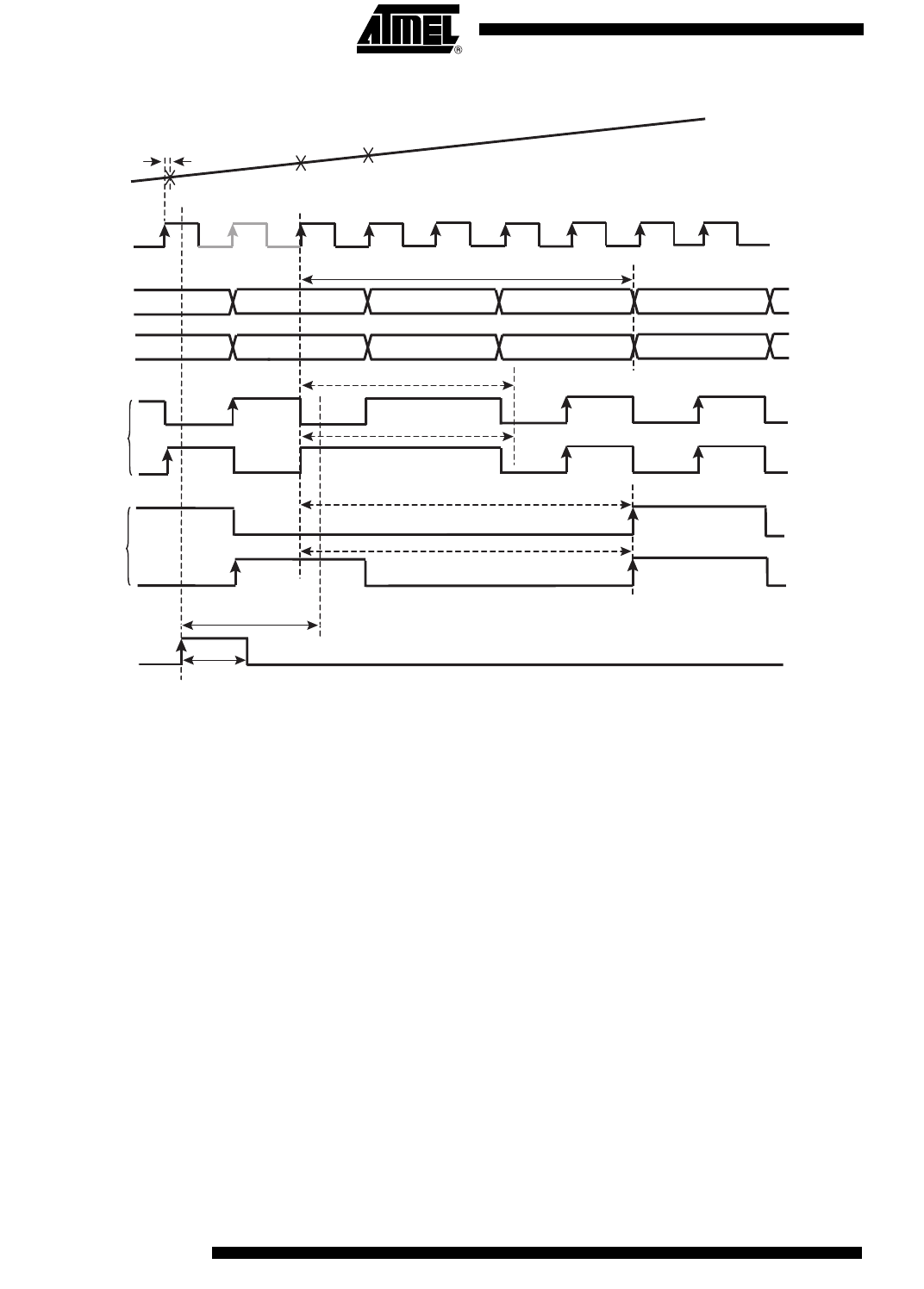
Figure 13. Data Ready Reset 1:2 DMUX Mode
Notes: 1. In 1:2 DMUX, Fs/2 mode:
The Data Ready Reset is taken into account only 2 ns after it is asserted. The output clock first completes its cycle (if the
reset occurs when it is low, it goes high only when its half cycle is complete; if the reset occurs when it is high, it remains
high) and then only, remains in reset state (frozen to a high level in 1:2 DMUX Fs/2 mode). The next rising edge of the input
clock after reset makes the output clock return to normal mode (after TDR).
2. In 1:2 DMUX, Fs/4 mode:
The Data Ready Reset is taken into account only 2 ns after it is asserted. The output clock first completes its cycle (if the
reset occurs when it is high, it goes low only when its half cycle is complete; if the reset occurs when it is low, it remains low)
and then only, remains in reset state (frozen to a low level in 1:2 DMUX Fs/4 mode). The next rising edge of the input clock
after reset makes the output clock return to normal mode (after TDR).
CLKI or
CLKQ
CLKOI or CLKOQ
(= CLKI/2)
DOIA[0:7] or
DOQA[0:7]
VIN
TA
N
N
DDRB
Pipeline Delay + TDO
N + 1
2 ns
DOIB[0:7] or
DOQB[0:7]
N + 1
CLKOI or CLKOQ
(= CLKI/4)
1 ns min
TDR
TDR
TDR + 2 cycles
TDR + 2 cycles
Clock in
Reset
PREVIOUS123456789101112NEXT