Freelance Electronics Components Distributor
Closed Dec 25th-26th
800-300-1968
We Stock Hard to Find Parts

AT84AD001BITD

Part # AT84AD001BITD
Description ADC DUAL FLASH 1GSPS 8BIT PARALLEL 144LQFP - Trays
Category IC
Availability Out of Stock
Qty 0
Qty Price
1 + $154.41500


Technical Document


DISCLAIMER: The information provided herein is solely for informational purposes. Customers must be aware of the suitability of this product for their application, and consider that variable factors such as Manufacturer, Product Category, Date Codes, Pictures and Descriptions may differ from available inventory.

43
AT84AD001B
2153C–BDC–04/04
The calibration phase is necessary when using the AT84AD001B in interlace mode,
where one analog input is sampled at both ADC cores on the common input clock’s ris
-
ing and falling edges. This operation is equivalent to converting the analog signal at
twice the clock frequency
During the ADC’s auto-calibration phase, the dual ADC is set with the following:
Decimation mode ON
1:1 DMUX mode
Binary mode
Any external action applied to any signal of the ADC’s registers is inhibited during the
calibration phase.
Gain and Offset
Compensation Functions
It is also possible for the user to have external access to the ADC’s gain and offset com-
pensation functions:
Offset compensation between I and Q channels (at address 010)
Gain compensation between I and Q channels (at address 011)
To obtain manual access to these two functions, which are used to set the offset to mid-
dle code 127.5 and to match the gain of channel Q with that of channel I (if only one
channel is used, the gain compensation does not apply), it is necessary to set the ADC
to “manual” mode by writing 0 at bits D11 and D10 of address 000.
Built-In Test (BIT) A Built-In Test (BIT) function is available to allow rapid testing of the device’s I/O by
either applying a defined static pattern to the ADC or by generating a dynamic ramp at
the ADC’s output. The dynamic ramp can be used with a clock frequency of up to
750 Msps. This function is controlled via the 3-wire bus interface at address 101.
The BIT is active when Data0 = 1 at address 110.
The BIT is inactive when Data0 = 0 at address 110.
The Data1 bit allows choosing between static mode (Data1 = 0) and dynamic mode
(Data1 = 1).
When the static BIT is selected (Data1 = 0), it is possible to write any 8-bit pattern by
defining the Data9 to Data2 bits. Port B then outputs an 8-bit pattern equal to Data9 ...
Data2, and Port A outputs an 8-bit pattern equal to NOT (Data9 ... Data2).
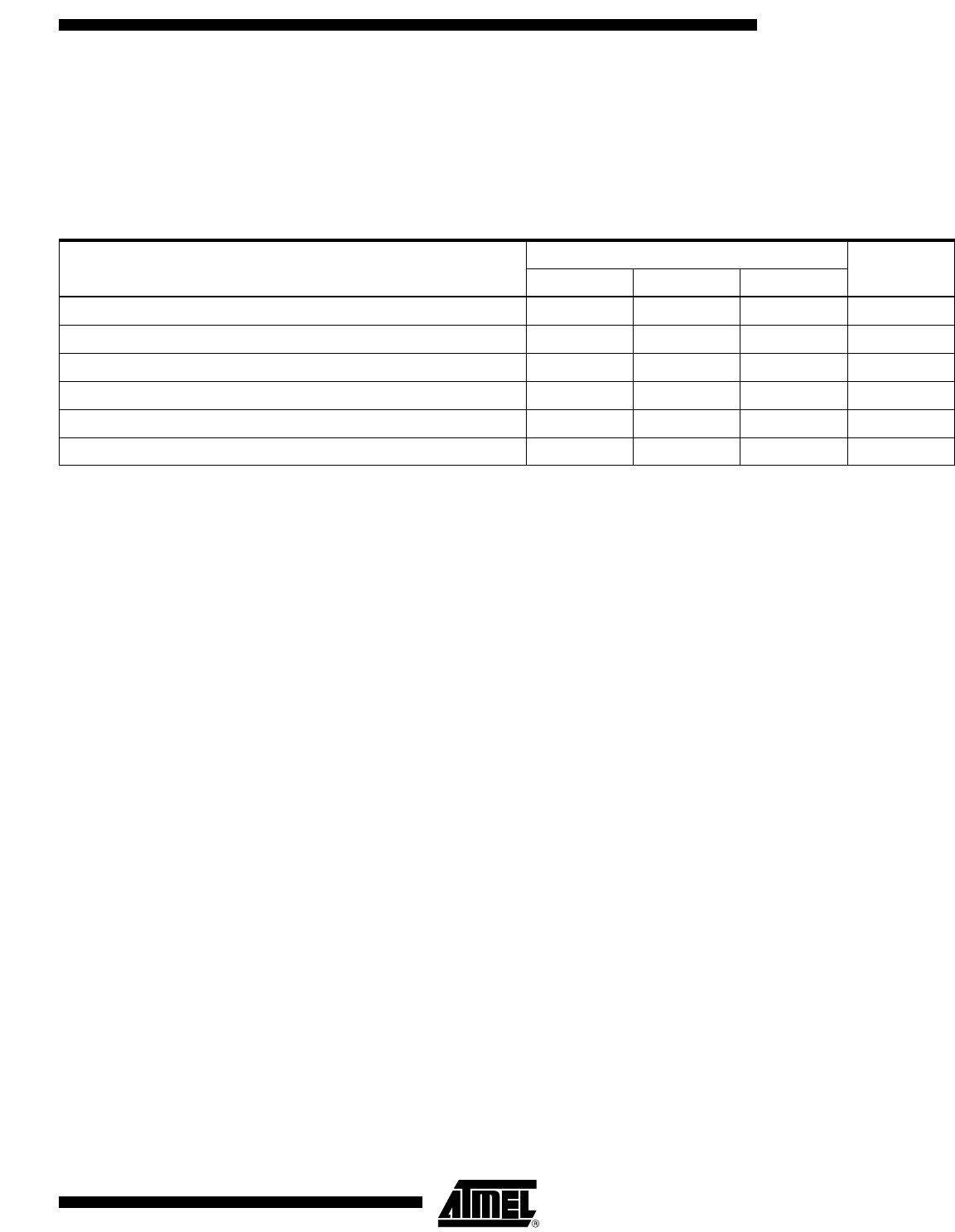
Table 15. Matching Between Channels
Parameter
Value
UnitMin Typ Max
Gain error (single channel I or Q) without calibration 0 LSB
Gain error (single channel I or Q) with calibration -0.5 0 0.5 LSB
Offset error (single channel I or Q) without calibration 0 LSB
Offset error (single channel I or Q) with calibration -0.5 0 0.5 LSB
Mean offset code without calibration (single channel I or Q) 127.5
Mean offset code with calibration (single channel I or Q) 127 127.5 128
44
AT84AD001B
2153C–BDC–04/04
Example:
Address = 110
Data =
One should then obtain 01010101 on Port B and 10101010 on Port A.
When the dynamic mode is chosen (Data1 = 1) port B outputs a rising ramp while Port A
outputs a decreasing one.
Note: In dynamic mode, use the DRDA function to align the edges of CLKO with the middle of
the data.
Decimation Mode The decimation mode is provided to enable rapid testing of the ADC at a maximum clock
frequency of 750 Msps. In decimation mode, one data out of 16 is output, thus leading to
a maximum output rate of 46.875 Msps.
Note: Frequency (CLKO) = frequency (Data) = Frequency (CLKI)/16.
Die Junction
Temperature Monitoring
Function
A die junction temperature measurement setting is included on the board for junction
temperature monitoring.
The measurement method forces a 1 mA current into a diode-mounted transistor.
Caution should be given to respecting the polarity of the current.
In any case, one should make sure the maximum voltage compliance of the current
source is limited to a maximum of 1V or use a resistor serial-mounted with the current
source to avoid damaging the transistor device (this may occur if the current source is
reverse-connected).
The measurement setup is illustrated in Figure 47.
Figure 47. Die Junction Temperature Monitoring Setup
D15 D14 D13 D12 D11 D10 D9 D8 D7 D6 D5 D4 D3 D2 D1 D0
XXXXXX0101010101
1 mA
GNDD
(Pin 36)
VDiode (Pin 35)
Protection
Diodes
45
AT84AD001B
2153C–BDC–04/04
The VBE diode’s forward voltage in relation to the junction temperature (in steady-state
conditions) is shown in Figure 48.
Figure 48. Diode Characteristics Versus T
J
VtestI, VtestQ VtestI and VtestQ pins are for internal test use only. These two signals must be left
open.
Equivalent Input/Output Schematics
Figure 49. Simplified Input Clock Model
620
640
660
680
700
720
740
760
780
800
820
840
860
-20-100 102030405060708090100110120
Junction Temperature (˚C)
Diode Voltage (mV)
VCCD/2
100
VCCD
GNDD
CLK
CLKB
100
50
50
PREVIOUS891011121314151617181920NEXT