Closed Dec 25th-26th
800-300-1968
We Stock Hard to Find Parts
My Account
|
My Orders
|
My Cart
Questions?
(800) 300-1968
Register
(current)
My Account
(current)
My Orders
(current)
My Cart
(current)
Categories
(current)
Manufacturers
Request a Quote
Sell Your Excess
Consignment
Quality Assurance
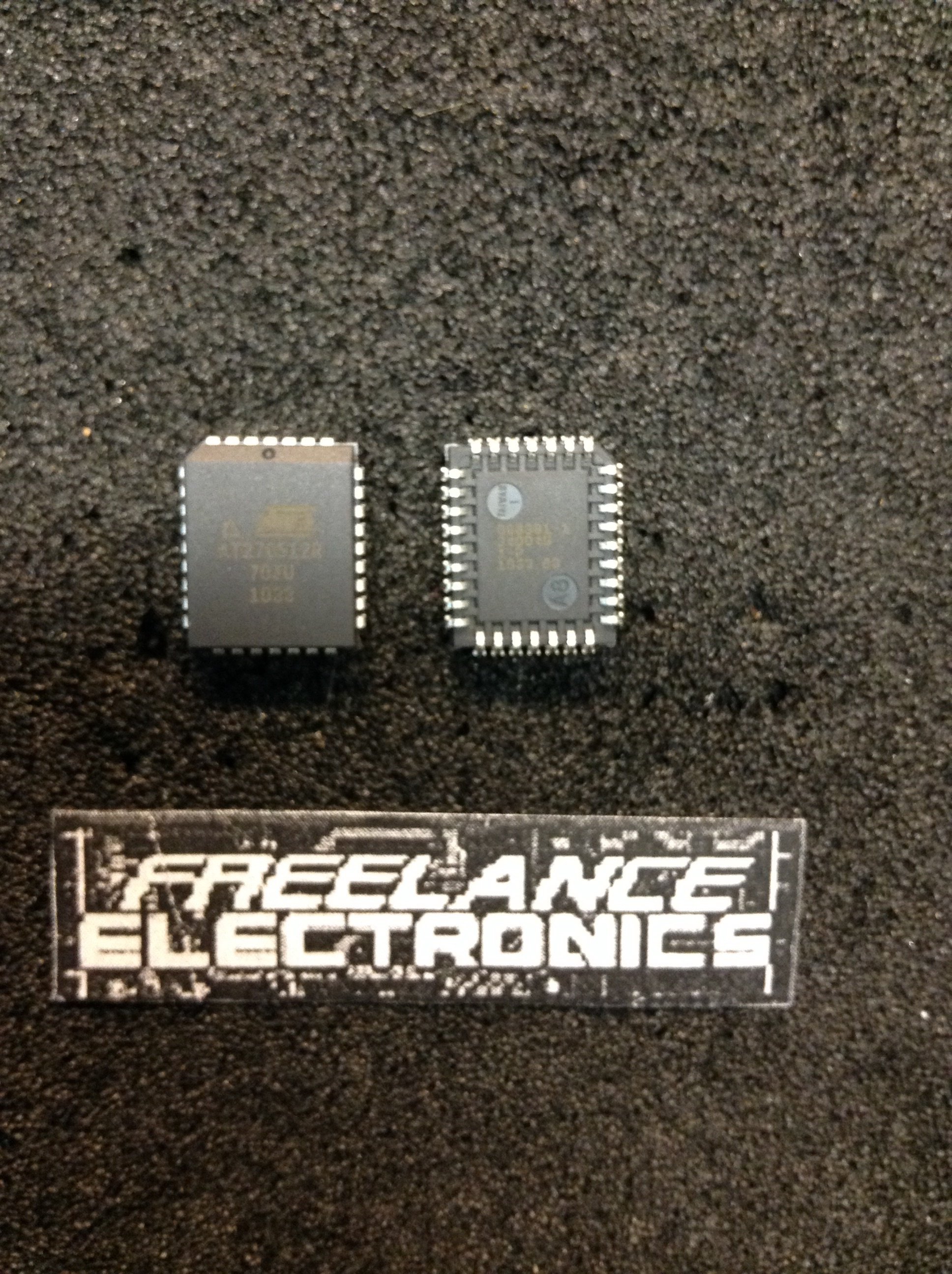
AT27C512R-70JU
Part #
AT27C512R-70JU
Description
EPROM OTP 512KBIT 64KX8 70NS32PLCC - Rail/Tube
Category
IC
Availability
Out of Stock
Qty
0
Qty
Price
1 +
$1.95120
Related Items
Atmel
IC
AT27C010-12J1
$4.59204
Atmel
IC
AT27C010-25KC
Atmel
IC
AT27C010-70JU
$3.00994
Atmel
IC
AT27C010-70PI
$17.95072
Atmel
IC
AT27C010L-15DC
Atmel
IC
AT27C010L-20TI
$6.55000