Freelance Electronics Components Distributor
Closed Dec 25th-26th
800-300-1968
We Stock Hard to Find Parts

AD724JR

Part # AD724JR
Description RGB TO NTSC AND PAL ENCODER 16SOIC W - Rail/Tube
Category IC
Availability In Stock
Qty 12
Qty Price
1 - 2 $20.55897
3 - 5 $16.44718
6 - 7 $13.56892
8 - 10 $12.60950
11 + $11.23890
Manufacturer Available Qty
Analog Devices
Date Code: 9738
  • Shipping Freelance Stock: 12
    Ships Immediately


Technical Document


DISCLAIMER: The information provided herein is solely for informational purposes. Customers must be aware of the suitability of this product for their application, and consider that variable factors such as Manufacturer, Product Category, Date Codes, Pictures and Descriptions may differ from available inventory.

REV. B
–10–
AD724
220mF
75V
75V
75V
–5V
FIN
OSC
0.1mF
+5V
**
CRYSTAL
0.1mF
+5V (V
AA
)
*
AGND
DGND
AD724
ENCD
RIN
GIN
BIN
HSYNC
VSYNC
SELECT
STND
CRMA
LUMA
CMPS
APOS
DPOS
10–30pF
0.1mF
10mF
0.1mF
10mF
75V75V
JMP
*
PARALLEL–RESONANT
CRYSTAL; 3.579545MHz (NTSC)
OR 4.433620MHz (PAL)
CAPACITOR VALUE DEPENDS ON
CRYSTAL CHOSEN
75V
COMPOSITE
VIDEO
75V
220mF
75V
220mF
Y
C
S-VIDEO
(Y/C VIDEO)
75V
75V
75V
B
G
R
RGB MONITOR
VSYNC
HSYNC
FROM VGA PORT
+5V
+5V
10kV
+5V
10kV
SELECT
75V
JMP
+5V
VGA OUTPUT
CONNECTOR
***
***
0.1mF CAPACITORS RECOMMENDED
649V649V
649V649V
649V649V
**
FSC OR 4FSC CLOCK; 3.579545MHz,
14.31818MHz (NTSC) OR 4.433620MHz,
17.734480MHz(PAL)
1/3
AD8013
1/3
AD8013
1/3
AD8013
0.1mF
0.1mF
0.1mF
Figure 15. Interfacing the AD724 to the (Interlaced) VGA Port of a PC
transmitted. Each output requires a 220 µF series capacitor to
work with the 75 resistance to pass these low frequencies. The
CRMA signal has information mostly up at the chroma fre-
quency and can use a smaller capacitor if desired, but 220 µF
can be used to minimize the number of different components
used in the design.
Displaying VGA Output on a TV
The AD724 can be used to convert the analog RGB output from a
personal computer’s VGA card to the NTSC or PAL television
standards. To accomplish this it is important to understand that
the AD724 requires interlaced RGB video and clock rates that
are consistent with those required by the television standards. In
most computers the default output is a noninterlaced RGB
signal at a frame rate higher than used by either NTSC or PAL.
Most VGA controllers support a wide variety of output modes
that are controlled by altering the contents of internal registers.
It is best to consult with the VGA controller manufacturer to
determine the exact configuration required to provide an inter-
laced output at 60 Hz (50 Hz for PAL).
Both the analog and digital ground pins should be tied to the
ground plane by a short, low inductance path. Each power
supply pin should be bypassed to ground by a low inductance
0.1 µF capacitor and a larger tantalum capacitor of about 10 µF.
The three analog inputs (RIN, GIN, BIN) should be terminated
with 75 to ground close to the respective pins. However, as
these are high impedance inputs, they can be in a loop-through
configuration. This technique is used to drive two or more
devices with high frequency signals that are separated by some
distance. A connection is made to the AD724 with no local
termination, and the signals are run to another distant device
where the termination for these signals is provided.
The output amplitudes of the AD724 are double that required
by the devices that it drives. This compensates for the halving of
the signal levels by the required terminations. A 75 series
resistor is required close to each AD724 output, while 75 to
ground should terminate the far end of each line.
The outputs have a dc bias and must be ac coupled for proper
operation. The COMP and LUMA outputs have information
down to 30 Hz for NTSC (25 MHz for PAL) that must be
AD724
REV. B
–11–
video from an MPEG decoder and creating both analog RGB
video and composite video.
The 24-bit wide RGB video is converted to analog RGB by
the ADV7120 (Triple 8-bit video DAC—available in 48-lead
LQFP). The analog current outputs from the DAC are termi-
nated to ground at both ends with 75 as called for in the data
sheet. These signals are ac coupled to the analog inputs of the
AD724. The HSYNC and VSYNC signals from the MPEG
Controller are directly applied to the AD724.
If the set of termination resistors closest to the AD724 are re-
moved, an RGB monitor can be connected to these signals and
will provide the required second termination. This is acceptable
as long as the RGB monitor is always present and connected. If
it is to be removed on occasion, another termination scheme is
required.
The AD8013 or AD8073 triple video op amp can provide buff-
ering for such applications. Each channel is set for a gain of two
while the outputs are back terminated with a series 75 resis-
tor. This provides the proper signal levels at the monitor, which
terminates the lines with 75 .
AD724 APPLICATION DISCUSSION—NTSC/PAL
CRYSTAL SELECT CIRCUIT
For systems that support both NTSC and PAL, and will use a
crystal for the subcarrier, a low cost crystal selection circuit can
be made that, in addition to the two crystals, requires two low
cost diodes, two resistors and a logic inverter gate. The circuit
selection can be driven by the STND signal that already drives
Pin 1 to select between NTSC and PAL operation for the AD724.
A schematic for such a circuit is shown in Figure 17. Each crys-
tal ties directly to FIN (Pin 3) with one terminal and has the
other terminal connected via a series diode to ground. Each
diode serves as a switch, depending on whether it is forward
biased or has no bias.
FIN
AGND
DGND
HSYNC
VSYNC
HSYNC
VSYNC
COMP
75V
220mF
COMPOSITE
VIDEO
CRMA
LUMA
75V
220mF
75V
220mF
S-VIDEO
10kV
AD724
ENCD
SELECT
STND
APOS DPOS
0.1mF 0.01mF
10–30pF
L1 (FERRITE BEAD)
+5V (V
AA
)
10mF 33mF
+5V (V
CC
)
GND
ADV7120
SYNC
CLOCK
BLANK
GND
24
DATA IN
HSYNC
VSYNC
+5V (V
AA
)
10kV
+5V
10kV
0.1mF
0.01mF
R
SET
550V
0.1mF
+5VV
AA
V
REF
FS
ADJ
COMP
0.1mF
+5V (V
AA
)
RIN
GIN
BIN
75V75V
75V
IOG
IOR
IOB
+5V
10kV
AD589
(1.2V REF)
+5V
0.1mF
+5V
CRYSTAL
*
PARALLEL–RESONANT CRYSTAL; 3.579545MHz (NTSC)
OR 4.433620MHz (PAL) CAPACITOR VALUE DEPENDS
ON CRYSTAL CHOSEN
**
*
75V75V
75V
***
***
0.1mF CAPACITORS RECOMMENDED
**
FSC OR 4FSC CLOCK; 3.579545MHz, 14.31818MHz (NTSC)
OR 4.433620MHz, 17.734480MHz(PAL)
OSC
MPEG
DECODER
0.1mF
0.1mF
0.1mF
Figure 16. AD724 and ADV7120/ADV7122 Providing MPEG Video Solution
Figure 15 shows a circuit for connection to the VGA port of a
PC. The RGB outputs are ac coupled to the respective inputs of
the AD724. These signals should each be terminated to ground
with 75 .
The standard 15-pin VGA connector has HSYNC on Pin 13
and VSYNC on Pin 14. These signals also connect directly to
the same name signals on the AD724. The FIN signal can be
provided by any of the means described elsewhere in the data
sheet. For a synchronous NTSC system, the internal 4FSC
(14.31818 MHz) clock that drives the VGA controller can be
used for FIN on the AD724. This signal is not directly accessible
from outside the computer, but it does appear on the VGA card.
If a separate RGB monitor is also to be used, it is not possible to
simply connect it to the R, G and B signals. The monitor pro-
vides a termination that would double terminate these signals.
The R, G and B signals should be buffered by three amplifiers
with high input impedances. These should be configured for a
gain of two, which is normalized by the divide-by-two termina-
tion scheme used for the RGB monitor.
The AD8013 is a triple video amplifier that can provide the
necessary buffering in a single package. It also provides a disable
pin for each amplifier, which can be used to disable the drive to
the RGB monitor when interlaced video is used (SELECT = LO).
When the RGB signals are noninterlaced, setting SELECT HI will
enable the AD8013 to drive the RGB monitor and disable the
encoding function of the AD724 via Pin 5. HSYNC and VSYNC
are logic level signals that can drive both the AD724 and RGB
monitor in parallel. If the disable feature is not required, the
AD8073 triple video op amp can provide a lower cost solution.
AD724 Used with an MPEG Decoder
MPEG decoding of compressed video signals is becoming a
more prevalent feature in many PC systems. To display images
on the computer monitor, video in RGB format is required.
However, to display the images on a TV monitor, or to record
the images on a VCR, video in composite format is required.
Figure 16 shows a schematic for taking the 24-bit wide RGB
REV. B
–12–
AD724
With the crystal selection circuit described above, the unse-
lected crystal and diode provide additional shunt capacitance
across the selected crystal. The evaluation board tested actually
required no additional capacitance in order to run at the
proper frequency for each video standard. However, depending
on the layout, some circuits might require a small capacitor
from FIN (Pin 3) to ground to operate with the chrominance
at the proper frequency.
SUBCARRIER FREQUENCY MEASUREMENT
It is extremely difficult to measure the oscillation frequency of
the AD724 when operating with a crystal. The only place where
a CW oscillation is present is at the FIN pin. However, probing
with any type of probe (even a low capacitance FET probe) at
this node will either kill the oscillation or change the frequency
of oscillation, so the unprobed oscillating frequency cannot be
discerned. Neither the composite video nor chroma signals have
the subcarrier represented in a CW fashion. (The LUMA signal
does not contain any of the subcarrier.) This makes it virtually
impossible to accurately measure the subcarrier frequency of
these signals with any oscilloscope technique.
Two methods have been found to accurately measure the sub-
carrier oscillating frequency. The first uses a spectrum analyzer
like the HP3585A that has an accurate frequency counter built
in. By looking at either the COMP or CHROMA output of the
AD724, a spectrum can be observed that displays the tone of
the subcarrier frequency as the largest lobe.
The CHROMA or COMP output of the AD724 should be
input into the spectrum analyzer either by means of a scope
probe into the 1␣ M input port or a 75␣ cable that can be
directly terminated by the 75␣ input termination selection of
the HP3585A. Each of these signals has present at least the
color burst signal on almost every line, which will be the domi-
nant tone in the frequency band near its nominal frequency.
Sidelobes will be observed on either side of the central lobe
spaced at 50␣ Hz (PAL) or 60␣ Hz (NTSC) intervals due to the
vertical scanning rate of the video signals. There will also be
sidelobes on either side at about 15.75␣ kHz intervals, but these
will not be observable with the span set to only a few kHz.
The center frequency of the spectrum analyzer should be set to
the subcarrier frequency of the standard that is to be observed.
The span should be set to 1␣ kHz–3 kHz and the resolution
bandwidth (RBW) set to between 10␣ Hz to 100 Hz. A combina-
tion of wider frequency span and narrower RBW will require a
long time for sweeping the entire range. Increasing the RBW
will speed up the sweep at the expense of widening the “humps”
in the subcarrier tone and the sideband tones.
Once the subcarrier is located, it can be moved to the center of
the display and the span can be narrowed to cover only that range
necessary to see it. The RBW can then be narrowed to produce
an acceptably fast sweep with good resolution.
The marker can now be placed at the location of the subcarrier
tone and the frequency counter turned on. The next scan across
the location of the marker will measure and display the subcarrier
frequency to better than 1␣ Hz resolution.
A second means for measuring the subcarrier frequency of an
AD724 operating from a crystal involves equipment more spe-
cialized than a spectrum analyzer. The technique requires a
Tektronix VM700A video system measurement instrument.
R1
10kV
Y1
Y2
CR1
IN4148
CR2
IN4148
STND
AD724
FIN
HC04
U1
OPTIONAL
NOTES: Y1 = 3.579545MHz
Y2 = 4.433620MHz
R2
10kV
PALNTSC
0-5pF
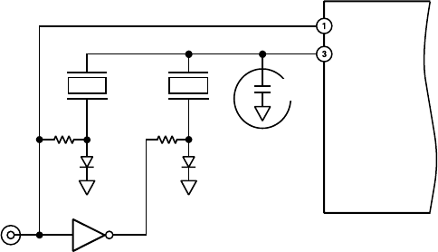
Figure 17.␣ Crystal Selection Circuit
Pin 1 (STND) of the AD724 is used to program the internal
operation for either NTSC (HIGH) or PAL (LOW). For NTSC
operation in this application the HIGH signal is also used to
drive R1 and the input of inverter U1. This creates a LOW
signal at the output of U1.
The HIGH (+5 V) signal applied to R1 forward biases CR1 with
approximately 450␣ µA of current. This turns the diode “on” (low
impedance with a forward voltage of approximately 0.6␣ V) and
selects Y1 as the crystal to run the oscillator on the AD724. The
bias across the diode does not affect the operation of the
oscillator.
The LOW (0 V) output of the inverter U1 is applied to R2. This
creates a 0 V bias condition across CR2 because its cathode is
also at ground potential. This diode is now in the “off” (high
impedance) state, because it takes approximately 600 mV of
forward bias to turn a diode “on” to any significant degree. The
“off” condition of the diode does, however, look like a capacitor
of a few pF.
For PAL operation, the STND signal that drives Pin 1 is set LOW
(0 V). This programs the AD724 for PAL operation, deselects the
NTSC crystal (Y1), because CR1 has no bias voltage across it and
selects the PAL crystal (Y2) by forward biasing CR2.
In order to ensure that the circuits described above operate
under the same conditions with either crystal selected, it is im-
portant to use a logic signal from a CMOS type logic family
whose output swings fully from ground to +5␣ V when operating
on a +5␣ V supply. Other TTL type logic families don’t swing
this far and might cause problems as a result of variations in the
diode bias voltages between the two different crystal selection
modes.
FREQUENCY TUNING
A parallel resonant crystal, is the type required for the AD724
oscillator, will work at its operating frequency when it has a
specified capacitance in parallel with its terminals. For the
AD724 evaluation board, it was found that approximately 10␣ pF
was required across either the PAL or NTSC crystal for proper
tuning. The parallel capacitance specified for these crystals is
17␣ pF for the NTSC crystal and 20␣ pF for the PAL crystal. The
parasitic capacitance of the PC board, packaging and the internal
circuitry of the AD724 appear to be contributing 7␣ pF–10 pF in
shunt with the crystal. A direct measurement of this was not
made, but the value is inferred from the measured results.
PREVIOUS12345NEXT