Closed Dec 25th-26th
800-300-1968
We Stock Hard to Find Parts
My Account
|
My Orders
|
My Cart
Questions?
(800) 300-1968
Register
(current)
My Account
(current)
My Orders
(current)
My Cart
(current)
Categories
(current)
Manufacturers
Request a Quote
Sell Your Excess
Consignment
Quality Assurance
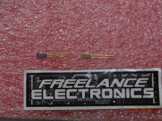
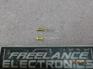
AD590MF
Part #
AD590MF
Description
MICROCIRCUIT
Category
IC
Availability
Out of Stock
Qty
0
Qty
Price
1 +
$33.39000
Related Items
ADI ELECTRONICS, INC.
IC
AD590J-DIE
$6.36456
Analog Devices
IC
AD590KF
$42.76000
Analog Devices
IC
AD590KF/883B
$46.14657
Analog Devices
IC
AD590KR
$11.08248
Analog Devices
IC
AD590LF/883B
$112.50510
Analog Devices
IC
AD590LH
$22.55430