Closed Dec 25th-26th
800-300-1968
We Stock Hard to Find Parts
My Account
|
My Orders
|
My Cart
Questions?
(800) 300-1968
Register
(current)
My Account
(current)
My Orders
(current)
My Cart
(current)
Categories
(current)
Manufacturers
Request a Quote
Sell Your Excess
Consignment
Quality Assurance
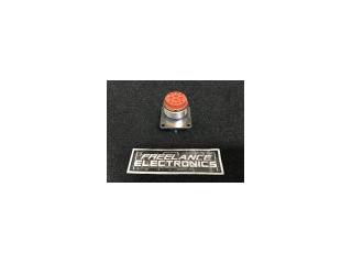
MS3470L18-32P
Part #
MS3470L18-32P
Description
CONN MIL-DTL-26482 CIRC PIN 32 POS CRMP ST WALL MNT 32TERM
Category
CONNECTOR
Availability
In Stock
Qty
3
Qty
Price
1 - 2
$65.57134
3 +
$49.67526
Manufacturer
Available
Qty
ITT CANNON
Date Code: 8614
Freelance Stock:
1
Ships Immediately
MATRIX
Date Code: 9212
Freelance Stock:
2
Ships Immediately
Add to Cart
Related Items
Deutsch Inc
CONNECTOR
MS3470E14-19P
$58.63866
Deutsch Inc
CONNECTOR
MS3470L10-6P
$33.40391
TSI
CONNECTOR
MS3470L12-10S
$47.42467
Bendix
CONNECTOR
MS3470L12-10SX
$62.36351
MCP
CONNECTOR
MS3470L14-05P
MATRIX
CONNECTOR
MS3470L14-12P
$39.79273