Freelance Electronics Components Distributor
Closed Dec 25th-26th
800-300-1968
We Stock Hard to Find Parts

87159-6

Part # 87159-6
Description
Category CONNECTOR
Availability Out of Stock
Qty 0
Qty Price
1 + $0.72320


Technical Document


DISCLAIMER: The information provided herein is solely for informational purposes. Customers must be aware of the suitability of this product for their application, and consider that variable factors such as Manufacturer, Product Category, Date Codes, Pictures and Descriptions may differ from available inventory.

286
1307819 Dimensions are in inches and Dimensions are shown for USA: 1-800-522-6752 Germany: 49-6251-133-1999
CIS WR 08/2011 millimeters unless otherwise reference purposes only. Canada: 1-905-475-6222 China: 86-400-820-6015
specified. Values in brackets Specifications subject Mexico: 52-55-1106-0800 Japan: 81-44-844-8013
te.com are metric equivalents. to change. L. & S. America: 54-11-4733-2200 UK: 44-800-267-666
AMPMODU Interconnection System
7
Mod I Receptacles, Board Mount, .031 x .062 [0.79 x 1.57] Centerline (Continued)
Note: All part numbers are RoHS compliant.
Mod I Receptacles,
Board Mount
Board Dimension
Standard Pressure High Pressure
Insertion
Type Thickness T Finish
Part Nos. Part Nos.
Applicator No. for
R
ange (Ref. Pg. 285 )
Strip Form Loose Piece Strip Form Loose Piece
U” Frame Machine
P
lating A 86477-2 86480-2 —— 466376-1
A .070-.055 [1.78-1.40] .112 [2.84] Plating B 86477-3 87316-3 466376-1
Plating C (Solder Resist) 87772-2 ——466376-1
Plating A 87003-1 87105-1 —— 466376-1
B .070-.055 [1.78-1.40] .112 [2.84] Plating B 87003-2 ——466376-1
Plating C (Solder Resist) 87774-2 ——466376-1
C
Plating A 85487-4 85493-4 86432-8 86434-6
565967-3
.103-.055 [2.62-1.40] .145 [3.68]
Plating B 85487-3 86432-1 86434-1
Notes: 1. All strip form parts in packaged quantities of 5,000 each.
2. All loose piece parts in packaged quantities of 500 each.
Material and Finish
Copper alloy, plated as follows:
Plating A — Selectively plated
.000030 [0.00076] gold on contact area,
with gold flash over .000050 [0.00127]
nickel on entire contact
Plating B — .000079 [0.00201] min.
tin on entire contact
Plating C — (Solder Resist) —
.000030 [0.00076] gold over .000050
[0.00127] nickel on contact area,
.000500 [0.01270] aluminum on inside
area of solder tines; remainder of contact
unfinished
S
tandard Pressure
Receptacle
H
igh Pressure
Receptacle
.010
[
0.25]
Max.
.020
[
0.51]
Max.
.210
[5.33]
.210
[
5.33]
287
1307819 Dimensions are in inches and Dimensions are shown for USA: 1-800-522-6752 Germany: 49-6251-133-1999
CIS WR 08/2011 millimeters unless otherwise reference purposes only. Canada: 1-905-475-6222 China: 86-400-820-6015
specified. Values in brackets Specifications subject Mexico: 52-55-1106-0800 Japan: 81-44-844-8013
te.com are metric equivalents. to change. L. & S. America: 54-11-4733-2200 UK: 44-800-267-666
AMPMODU Interconnection System
7
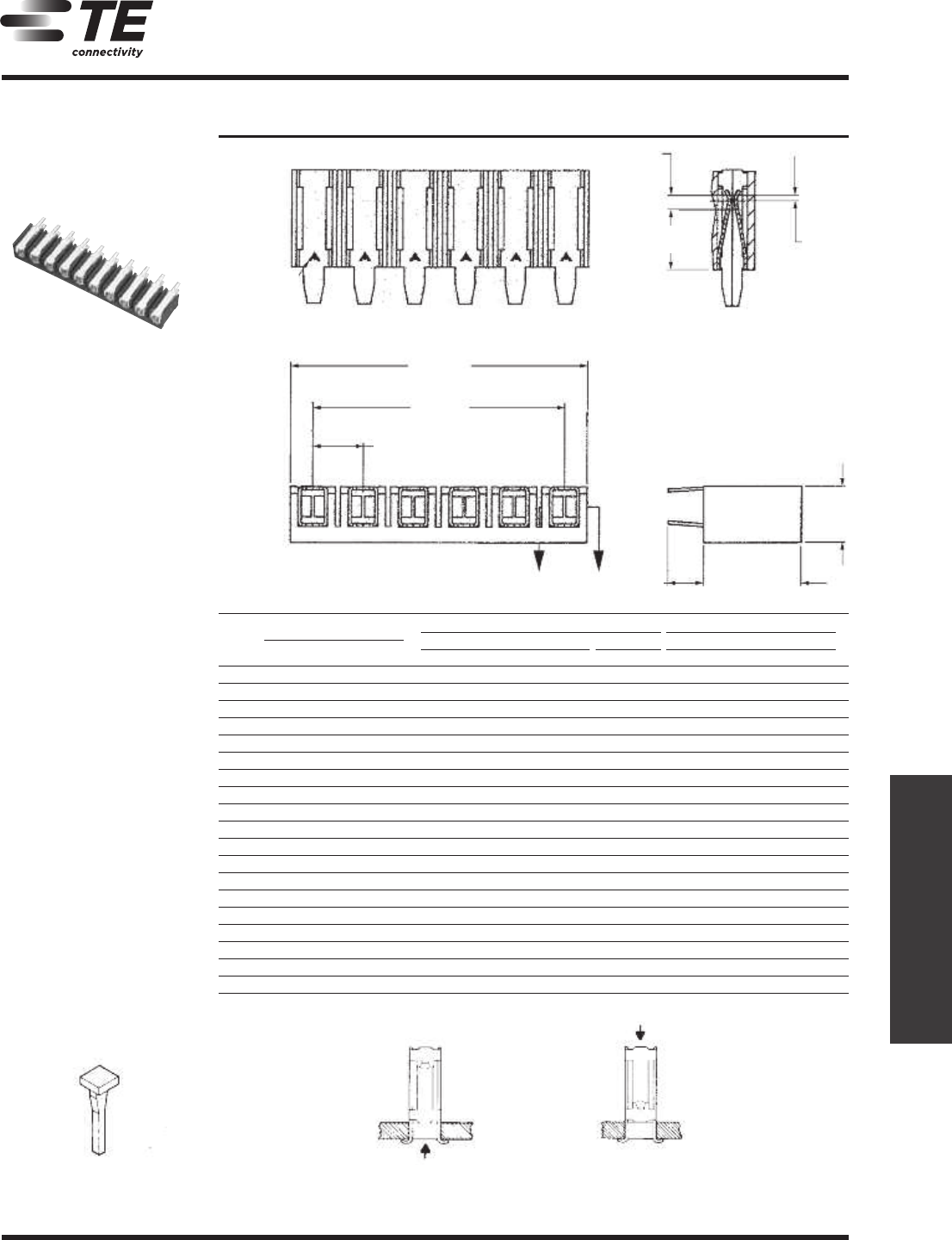
Mod I Receptacle Assemblies, Vertical Board Mount,
.031 x .062 [0.79 x 1.57] Centerline
Note: All part numbers are RoHS compliant.
Mod I Receptacles,
Vertical Board Mount
No.
Dimensions
Type A Type B
of Standard Pressure High Pressure Standard Pressure
Pos.
AB
Plating A Plating B Plating C Plating B Plating A Plating B Plating C
2 .156 [3.96] .312 [7.92] 87984-2 87983-2 87989-2 87993-2 87986-2 87985-2 87990-2
3 .312 [7.92] .468 [11.89] 87984-3 87983-3 87989-3 87993-3 87986-3 87985-3 87990-3
4 .468 [11.89] .624 [15.85] 87984-4 87983-4 87989-4 87993-4 87986-4 87985-4 87990-4
5 .624 [15.85] .780 [19.81] 87984-5 87983-5 87989-5 87993-5 87986-5 87985-5 87990-5
6 .780 [19.81] .936 [23.77] 87984-6 87983-6 87989-6 87993-6 87986-6 87985-6 87990-6
7 .936 [23.77] 1.092 [27.74] 87984-7 87983-7 87989-7 87993-7 87986-7 87985-7 87990-7
8 1.092 [27.74] 1.248 [31.70] 87984-8 87983-8 87989-8 87993-8 87986-8 87985-8 87990-8
9 1.248 [31.70] 1.404 [35.66] 87984-9 87983-9 87989-9 87993-9 87986-9 87985-9 87990-9
10 1.404 [35.66] 1.560 [39.62] 1-87984-0 1-87983-0 1-87989-0 1-87993-0 1-87986-0 1-87985-0 1-87990-0
11 1.560 [39.62 1.716 [43.59] 1-87984-1 1-87983-1 1-87989-1 1-87993-1 1-87986-1 1-87985-1 1-87990-1
12 1.716 [43.59] 1.872 [47.55] 1-87984-2 1-87983-2 1-87989-2 1-87993-2 1-87986-2 1-87985-2 1-87990-2
13 1.872 [47.55] 2.028 [51.51] 1-87984-3 1-87983-3 1-87989-3 1-87993-3 1-87986-3 1-87985-3 1-87990-3
14 2.028 [51.51] 2.184 [55.47] 1-87984-4 1-87983-4 1-87989-4 1-87993-4 1-87986-4 1-87985-4 1-87990-4
15 2.184 [55.47] 2.340 [59.44] 1-87984-5 1-87983-5 1-87989-5 1-87993-5 1-87986-5 1-87985-5 1-87990-5
16 2.340 [59.44] 2.496 [63.40] 1-87984-6 1-87983-6 1-87989-6 1-87993-6 1-87986-6 1-87985-6 1-87990-6
17 2.496 [63.40] 2.652 [67.36] 1-87984-7 1-87983-7 1-87989-7 1-87993-7 1-87986-7 1-87985-7 1-87990-7
18 2.652 [67.36] 2.808 [71.32] 1-87984-8 1-87983-8 1-87989-8 1-87993-8 1-87986-8 1-87985-8 1-87990-8
19 2.808 [71.32] 2.964 [75.29] 1-87984-9 1-87983-9 1-87989-9 1-87993-9 1-87986-9 1-87985-9 1-87990-9
20 2.964 [75.29] 3.120 [79.25] 2-87984-0 2-87983-0 2-87989-0 2-87993-0 2-87986-0 2-87985-0 2-87990-0
Single Row .156 [3.96]
Centerline
Material and Finish
Housing — Black thermoplastic, 94V-0
rated
Contacts — Copper alloy, plated as
follows:
Plating A — Selectively plated
.000030 [0.00076] gold on contact area,
with gold flash over .000050 [0.00127]
nickel on entire contact
Plating B — .000079 [0.00201] min.
tin on entire contact
Plating C — (Solder Resist) —
.000030 [0.00076] gold over .000050
[0.00127] nickel on contact area,
.000500 [0.01270] aluminum on inside
area of solder tines; remainder of contact
unfinished
Related Product Data
Recommended Board Layout
page 288
Mates with
Machine Applied Posts — page 294
Headers — pages 295-297
Performance Specifications
page 305
Technical Documents
page 305
Part No. 86181-2
(Use in Board Mount
Receptacles)
Post Entry
Type A
Post Entry
Type B
Keying Plug
X-X
X X
.182
[
4.62]
.018
[0.46]
.175±.007
[4.45±0.18]
.
300±.003
[7.62±0.08]
.
046
[1.17]
Contact
A
rea
B
±.015
[±0.38]
A
.156
[3.96]
T
yp.
T
he letter A
stamped on
contact indicates
m
ating end of
receptacle.
.112-.000
[2.84±0.00]
+.010
+0.25
288
1307819 Dimensions are in inches and Dimensions are shown for USA: 1-800-522-6752 Germany: 49-6251-133-1999
CIS WR 08/2011 millimeters unless otherwise reference purposes only. Canada: 1-905-475-6222 China: 86-400-820-6015
specified. Values in brackets Specifications subject Mexico: 52-55-1106-0800 Japan: 81-44-844-8013
te.com are metric equivalents. to change. L. & S. America: 54-11-4733-2200 UK: 44-800-267-666
AMPMODU Interconnection System
7
Mod I Receptacle Assemblies, Horizontal Board Mount,
.031 x .062 [0.79 x 1.57] Centerline
Note: All part numbers are RoHS compliant.
Mod I Receptacles,
Horizontal Board Mount
Single Row .156 [3.96]
Centers
Material and Finish
Housing — Black thermoplastic, 94V-0
rated
Contacts — Copper alloy, plated as
follows:
Plating A — Selectively plated
.000030 [0.00076] gold contact area,
with gold flash over .000050 [0.00127]
nickel on entire contact
Plating B — .000079 [0.00201] min.
tin on entire contact
Related Product Data
Mates with
Machine Applied Posts — page 294
Headers — pages 295-297
Performance Specifications
page 305
Technical Documents
page 305
Recommended Board
Layouts for Receptacle
Assemblies and Individual
Receptacles (Type C)
The mating post length is depicted by the A dimension on page 294 (machine applied posts) and the C dimension on
pages 295-297 (headers).
H-Receptacle centers may vary depending on requirements. For individual receptacles, minimum nominal centerline
spacing between adjacent receptacles is .125 [3.18] for receptacle assemblies, centerline spacing between adjacent
receptacles is .156 [3.96]. The .003 [0.08] tolerances are not to accumulate over length of board.
This configuration recommended
for use with machine applied posts
or headers with a .500 [12.70]
minimum mating end post length.*
This configuration recommended
for use with machine applied posts
or headers with a .345 [18.76]
minimum mating end post length.*
This configuration recommended
for use with machine applied posts
or headers with a .405 [10.29]
minimum mating end post length.*
Post Entry
T
ype C
Part No. 86181-2
(Use in Board Mount
Receptacles)
Keying Plug
H
±.003
[±0.08]
.055±.005
[1.40±0.13]
.340
+.005
-.000
]
2H
±.003
[±0.08]
[
[8.64+0.13]
H
±.003
[±0.08]
.340
+.005
-.000
]
2H
±.003
[±0.08]
[
[8.64+0.13]
H
±.003
[±0.08]
.073±.003
[1.85±0.08]
Typ. Dia.
.100
[2.54]
Max.
.073±.003
[1.85±0.08]
Typ. Dia.
.073±.003
[1.85±0.08]
Typ. Dia.
.340
+.005
-.000
]
2H
±.003
[±0.08]
[
[8.64+0.13]
X-X
X X
.
182
[4.62]
.
145
[3.68]
.
300±.003
[7.62±0.08]
.
175±.007
[4.45±0.18]
.
333±.010
[8.46±0.25]
.
018
[0.46]
.
046
[1.17]
Contact
A
rea
B
±
.015
[±0.38]
A
.
156
[3.96]
Typ.
The letter A stamped
on contact indicates
m
ating end of recep-
tacle.
PREVIOUS8990919293949596979899100101102NEXT