Freelance Electronics Components Distributor
Closed Dec 25th-26th
800-300-1968
We Stock Hard to Find Parts

87159-6

Part # 87159-6
Description
Category CONNECTOR
Availability Out of Stock
Qty 0
Qty Price
1 + $0.72320


Technical Document


DISCLAIMER: The information provided herein is solely for informational purposes. Customers must be aware of the suitability of this product for their application, and consider that variable factors such as Manufacturer, Product Category, Date Codes, Pictures and Descriptions may differ from available inventory.

256
1307819 Dimensions are in inches and Dimensions are shown for USA: 1-800-522-6752 Germany: 49-6251-133-1999
CIS WR 08/2011 millimeters unless otherwise reference purposes only. Canada: 1-905-475-6222 China: 86-400-820-6015
specified. Values in brackets Specifications subject Mexico: 52-55-1106-0800 Japan: 81-44-844-8013
te.com are metric equivalents. to change. L. & S. America: 54-11-4733-2200 UK: 44-800-267-666
AMPMODU Interconnection System
5
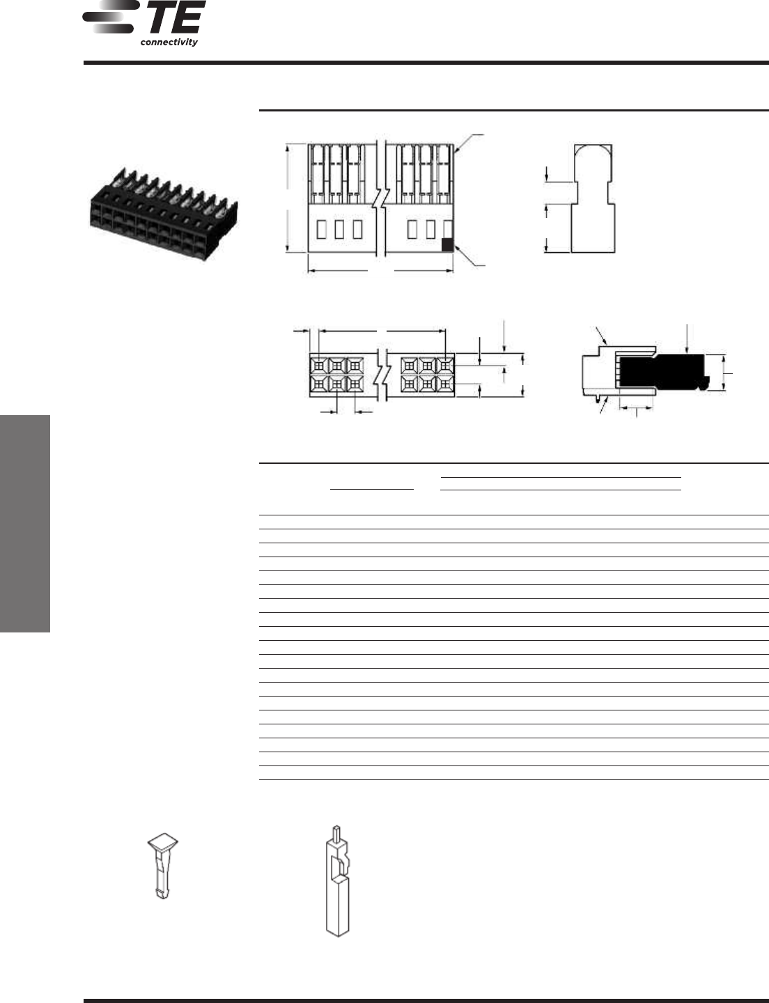
MT Receptacle Assemblies, Double-Row
.100 x .100 [2.54 x 2.54] Centerline
Note: All part numbers are RoHS compliant.
MT Receptacle Assemblies
Material and Finish
Housing — Glass-filled thermoplastic,
black, 94V-0 rated
Contacts — Copper alloy, duplex
plated .000030 [0.00076] gold in mating
area, .000050 [0.00127] tin on solder
tail, with entire contact underplated
.000050 [0.00127] nickel
Related Product Data
Mateable Connectors — pages 117,
122, 126, 130, 264
Cable Insulation Wall
Thickness — .015 [0.39] max.
Cable Insulation Diameter
.050 [1.27] max.
Mating Post Length
.222-.273 [5.64-6.94] max.
Performance Characteristics
page 255
Replacement Contacts — page 265
Connector Covers
pages 258, 259
Application Tooling
pages 273-275
Technical Documents
pages 277, 278
Product Specification
108-25015, 108-25018, 108-25030
Application Specification
114-25032
Instruction Sheet
408-6532
Housings Pre-loaded with
Standard Pressure Contacts
A
Max.
1
B
.100
[2.54]
.600
[
15.24]
.125
[
3.18]
.100
[
2.54]
Typ.
.270
[6.86]
Part Nos. (Stamped)
No. of
Dimensions
Wire Size Range Unloaded
Pos.
AB
30-26 AWG 26-22 AWG 22-20 AWG
Housings
[0.05-0.15 mm
2
] [0.12-0.3 mm
2
] [0.3-0.6 mm
2
]
6 .300 [7.62] .200 [5.08] 5-102393-1 5-102398-1 5-102448-1 102394-1
8 .400 [10.16] .300 [7.62] 5-102393-2 5-102398-2 5-102448-2 102394-2
10 .500 [12.70] .400 [10.16] 5-102393-3 5-102398-3 5-102448-3 102394-3
12 .600 [15.24] .500 [12.70] 5-102393-4 5-102398-4 5-102448-4 102394-4
14 .700 [17.78] .600 [15.24] 5-102393-5 5-102398-5 5-102448-5 102394-5
16 .800 [20.32] .700 [17.78] 5-102393-6 5-102398-6 5-102448-6 102394-6
18 .900 [22.86] .800 [20.32] 5-102393-7 5-102398-7 5-102448-7 102394-7
20 1.000 [25.40] .900 [22.86] 5-102393-8 5-102398-8 5-102448-8 102394-8
22 1.100 [27.94] 1.000 [25.40] 5-102393-9 5-102398-9 5-102448-9 102394-9
24 1.200 [30.48] 1.100 [27.94] 6-102393-0 6-102398-0 6-102448-0 1-102394-0
26 1.300 [33.02] 1.200 [30.48] 6-102393-1 6-102398-1 6-102448-1 1-102394-1
28 1.400 [35.56] 1.300 [33.02] 6-102393-2 6-102398-2 6-102448-2 1-102394-2
30 1.500 [38.10] 1.400 [35.56] 6-102393-3 6-102398-3 6-102448-3 1-102394-3
32 1.600 [40.64] 1.500 [38.10] 6-102393-4 6-102398-4 6-102448-4 1-102394-4
34 1.700 [43.18] 1.600 [40.64] 6-102393-5 6-102398-5 6-102448-5 1-102394-5
40 2.000 [50.80] 1.900 [48.26] 6-102393-8 6-102398-8 6-102448-8 1-102394-8
50 2.500 [63.50] 2.400 [60.96] 7-102393-3 7-102398-3 7-102448-3 2-102394-3
60 3.000 [76.20] 2.900 [73.66] 7-102393-8 7-102398-8 7-102448-8 2-102394-8
64 3.200 [81.28] 3.100 [78.74] 8-102393-0 8-102398-0 8-102448-0 3-102394-0
Note: Contact Extraction/Lance Reset Tool No. 843477-3, see page 265.
Part No. 86286-1
(Plugs into receptacle contact)
Material — Natural color nylon
Keying Plugs
Part No. 87077-2
(Plugs directly into housing)
11111
1
Circuit No. 1
I
dentifier
Contact
I.D. No.
.050
[
1.27]
.070
[
1.78]
.240
[6.10]
Right-Angle
Header
MT Receptacle
A
ssembly
P
C
Board
.
270
[6.86]
.
300
[7.62]
257
1307819 Dimensions are in inches and Dimensions are shown for USA: 1-800-522-6752 Germany: 49-6251-133-1999
CIS WR 08/2011 millimeters unless otherwise reference purposes only. Canada: 1-905-475-6222 China: 86-400-820-6015
specified. Values in brackets Specifications subject Mexico: 52-55-1106-0800 Japan: 81-44-844-8013
te.com are metric equivalents. to change. L. & S. America: 54-11-4733-2200 UK: 44-800-267-666
AMPMODU Interconnection System
5
MT Receptacle Assemblies, Double-Row
.100 x .100 [2.54 x 2.54] Centerline
(Continued)
Note: All part numbers are RoHS compliant.
MT Receptacle Assemblies
Material and Finish
Housing — Glass-filled thermoplastic,
black, 94V-0 rated
Contacts — Copper alloy, duplex
plated .000030 [0.00076] gold in mating
area, .000050 [0.00127] tin on solder
tails, with entire contact underplated
.000050 [0.00127] nickel
Related Product Data
Mateable Connectors — pages 117,
122, 126, 130, 264
Cable Insulation Wall
Thickness — .015 [0.39] max.
Cable Insulation Diameter
.050 [1.27] max.
Mating Post Length
.200-.273 [5.64-6.94] max.
Performance Characteristics
page 255
Replacement Contacts — page 265
Connector Covers
pages 258, 259
Application Tooling
pages 273-275
Technical Documents
pages 277, 278
Product Specification
108-25015, 108-25018, 108-25030
Application Specification
114-25032
Instruction Sheet
408-6532
Housings Pre-loaded with
High Pressure Contacts
A Max.
4
B
.100
[2.54]
.
600
[15.24]
.125
[3.18]
.100
[2.54]
T
yp.
.270
[
6.86]
Part Nos. (Stamped*)
No. of
Dimensions
Wire Size Range
Pos.
AB
30-26 AWG 26-22 AWG 22-20 AWG
[0.05-0.15 mm
2
] [0.12-0.3 mm
2
] [0.3-0.6 mm
2
]
6 .300 [7.62] .200 [5.08] 5-102693-1 5-102694-1 5-102695-1
8 .400 [10.16] .300 [7.62] 5-102693-2 5-102694-2 5-102695-2
10 .500 [12.70] .400 [10.16] 5-102693-3 5-102694-3 5-102695-3
12 .600 [15.24] .500 [12.70] 5-102693-4 5-102694-4 5-102695-4
14 .700 [17.78] .600 [15.24] 5-102693-5 5-102694-5 5-102695-5
16 .800 [20.32] .700 [17.78] 5-102693-6 5-102694-6 5-102695-6
18 .900 [22.86] .800 [20.32] 5-102693-7 5-102694-7 5-102695-7
20 1.000 [25.40] .900 [22.86] 5-102693-8 5-102694-8 5-102695-8
*Cavity identification — first cavity (one side); TE Part No. and date code stamped on housing where size permits.
Note: Contact Extraction/Lance Reset Tool No. 843477-3, see page 265.
Part No. 86286-1
(Plugs into receptacle contact)
Material — Natural color nylon
Keying Plugs
Part No. 87077-2
(Plugs directly into housing)
1
C
ircuit No. 1
Identifier
Contact
I.D. No.
.050
[
1.27]
.240
[
6.10]
Right-Angle
H
eader
M
T Receptacle
Assembly
PC
Board
.270
[6.86]
.300
[7.62]
444 44444 4
258
1307819 Dimensions are in inches and Dimensions are shown for USA: 1-800-522-6752 Germany: 49-6251-133-1999
CIS WR 08/2011 millimeters unless otherwise reference purposes only. Canada: 1-905-475-6222 China: 86-400-820-6015
specified. Values in brackets Specifications subject Mexico: 52-55-1106-0800 Japan: 81-44-844-8013
te.com are metric equivalents. to change. L. & S. America: 54-11-4733-2200 UK: 44-800-267-666
AMPMODU Interconnection System
5
Low Profile Covers for Double-Row MT Receptacle Assemblies
Note: All part numbers are RoHS compliant.
MT Low Profile Covers
L
L
.750
[19.05]
Material
Black thermoplastic, flame retardant
Related Product Data
For use on Double-Row MT Receptacle
Assemblies — pages 256, 257
Technical Documents
pages 277, 278
Product Specification
108-25015, 108-25018, 108-25030
Application Specification
114-25032
Instruction Sheet
408-6532
N
ote: See page 259 for Low Profile
Cover Part Nos.
Front Covers
.095
[
2.41]
Typ.
.468
[11.89]
.150
[3.81]
.
750
[19.05]
.
750
[19.05]
.750
[19.05]
A
ssembled*
L L
.
480
[12.19]
A - Polarizing Cover
(
Mates with AMPMODU 4-sided shrouded
headers. Refer to pages 117, 122, 126, 130.)
B - Latching Cover
(
Mates with AMPMODU 4-sided shrouded
headers with extraction slot. Refer to
p
ages 117, 122, 126, 130.)
C
- Ejection Cover
(Mates with AMP-LATCH universal ejection
s
tyle pin headers equipped with latching
ears, Part No. 102185-2 (with push tabs)
or Part No. 102312-2 (without push tabs),
s
ee TE Catalog 82012.
D
- Non-Polarizing Cover
(Designed for use with shielded connectors,
p
ages 261 & 262; or for non-polarizing
applications.)
*Dimension applies to cover when
installed on connector housing.
Back Covers
E - For Shielding and
Non-Shielding Applications
(For use with any low profile cover.)
F - For Shielding Applications
(For use with Non-Polarizing Cover only.)
PREVIOUS7980818283848586878889909192NEXT