204
1307819 Dimensions are in inches and Dimensions are shown for USA: 1-800-522-6752 Germany: 49-6251-133-1999
CIS WR 08/2011 millimeters unless otherwise reference purposes only. Canada: 1-905-475-6222 China: 86-400-820-6015
specified. Values in brackets Specifications subject Mexico: 52-55-1106-0800 Japan: 81-44-844-8013
te.com are metric equivalents. to change. L. & S. America: 54-11-4733-2200 UK: 44-800-267-666
AMPMODU Interconnection System
5
Accessories: Barrier Insert, Part No. 87743-1
Note: All part numbers are RoHS compliant.
Printed Circuit Board
Connectors
Material
Black polyester
Technical Documents
— page 276
The barrier insert can be
used on double row headers
(.100 x .100 [2.54 x 2.54]
centers), including shrouded
versions—3 and 4 sides,
as well as unshrouded
straight post headers. With
o
ne barrier insert several
configurations can be
obtained, providing headers
with capabilities of accept-
ing various combinations of
polarized and non-polarized
AMPMODU connectors.
For unshrouded headers,
the barrier insert is used
to establish polarization
and to compartmentalize
the header. For shrouded
headers, the barrier insert is
used to compartmentalize
the header, while maintaining
polarization. The barrier
insert itself is notched to
facilitate cutting off the
ends with a simple tool
such as tin snips or scissors
to achieve the desired
configuration.
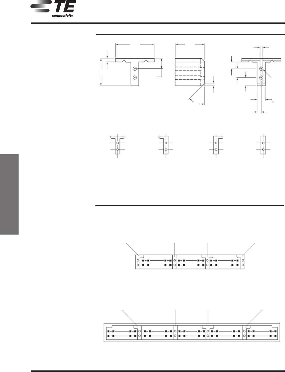
Barrier Insert Cutoffs
Fig. 1
Partial Cutoff
(Left and Right Sides)
F
ig. 2
Partial Cutoff
(Left Side)
Complete Cutoff
(Right Side)
F
ig. 3
Complete Cutoff
(Left Side)
Partial Cutoff
(Right Side)
F
ig. 4
Complete Cutoff
(Left and Right Sides)
Typical Barrier Insert Applications
For Unshrouded Double-Row, Straight Post Headers,
.100 x .100 [2.54 x 2.54] Centers
For Shrouded Double-Row, 3 and 4 Sided Headers,
.100 x .100 [2.54 x 2.54] Centers
Note: All configurations of barrier inserts compartmentalize headers and maintain polarization,
except bar (Fig. 4) configuration, which is used primarily for compartmentalizing headers.
Note: Right-angle (Figs. 2 and 3) and “T” (Fig. 1) configurations of barrier insert establish
polarization; bar (Fig. 4) configuration of barrier insert compartmentalizes header.
.
446
[11.33]
.037
[0.94]
.314
[7.98]
.
127
[3.23]
.340
[
8.64]
.030
[
0.76]
45°
.
030
[0.76]
.
090
[2.29]
.100
[2.54]
.087
[
2.21]
.
047
[1.19]
.094
[
2.39]
See Fig. 3 See Fig. 4 See Fig. 1 See Fig. 2
See Fig. 2 See Fig. 4 See Fig. 1 See Fig. 3
.031-.043
[0.79-1.09]
Dia. x .250[
[6.35]
Deep—
remainder
.029±.001
[0.74±0.03]
Dia.
Thru Typ. (2)


