Closed Dec 25th-26th
800-300-1968
We Stock Hard to Find Parts
My Account
|
My Orders
|
My Cart
Questions?
(800) 300-1968
Register
(current)
My Account
(current)
My Orders
(current)
My Cart
(current)
Categories
(current)
Manufacturers
Request a Quote
Sell Your Excess
Consignment
Quality Assurance
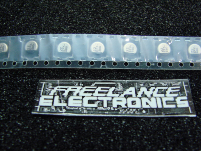
EEE-FK1E220R
Part #
EEE-FK1E220R
Description
CAP ALUM 22UF 20% 25V SMD
Additional Information:
Category
CAPACITOR
Availability
Out of Stock
Qty
0
Qty
Price
1 +
$0.04664
Related Items
PANASONIC ELECTRONICS
CAPACITOR
EEE-FC1A151P
$0.14818
PANASONIC ELECTRONICS
CAPACITOR
EEE-FK0J101UR
$0.05468
PANASONIC ELECTRONICS
CAPACITOR
EEE-FK0J470UR
$0.02276
PANASONIC ELECTRONICS
CAPACITOR
EEE-FK1C470UR
$0.06297
PANASONIC ELECTRONICS
CAPACITOR
EEE-FK1C472AM
$2.30315
PANASONIC ELECTRONICS
CAPACITOR
EEE-FK1H221P
$0.17000