Closed Dec 25th-26th
800-300-1968
We Stock Hard to Find Parts
My Account
|
My Orders
|
My Cart
Questions?
(800) 300-1968
Register
(current)
My Account
(current)
My Orders
(current)
My Cart
(current)
Categories
(current)
Manufacturers
Request a Quote
Sell Your Excess
Consignment
Quality Assurance
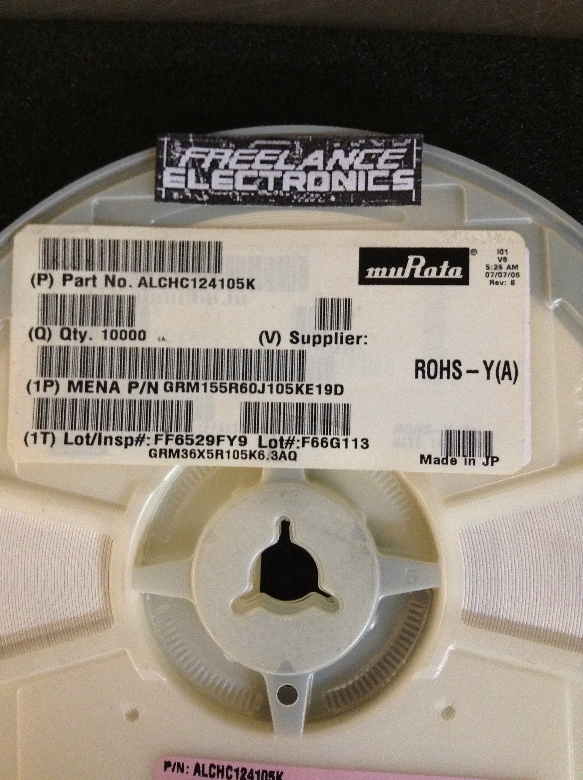
GRM155R60J105KE19D
Part #
GRM155R60J105KE19D
Description
CAP 1UF 6.3VDC X5R 10% SMD 0402 - Cut TR (SOS)
Additional Information:
Category
CAPACITOR
Availability
Out of Stock
Qty
0
Qty
Price
1 +
$0.00900
Related Items
MURATA
CAPACITOR
GRM1555C1H101JD01D
$0.01800
MURATA
CAPACITOR
GRM1555C1H180JA01D
$0.02398
MURATA
CAPACITOR
GRM1555C1H270JZ01D
$0.01386
MURATA
CAPACITOR
GRM1555C1H5R0CZ01D
$0.09644
MURATA
CAPACITOR
GRM1555C1H751JA01D
$0.02042
MURATA
CAPACITOR
GRM155R60J225ME15D
$0.24141