Closed Dec 25th-26th
800-300-1968
We Stock Hard to Find Parts
My Account
|
My Orders
|
My Cart
Questions?
(800) 300-1968
Register
(current)
My Account
(current)
My Orders
(current)
My Cart
(current)
Categories
(current)
Manufacturers
Request a Quote
Sell Your Excess
Consignment
Quality Assurance
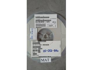
ECJ-1VB1C683K
Part #
ECJ-1VB1C683K
Description
CAP CER 0.068UF 16V 10% X7R 0603
Additional Information:
Category
CAPACITOR
Availability
In Stock
Qty
530
Qty
Price
1 +
$0.02056
Manufacturer
Available
Qty
PANASONIC ELECTRONICS
Freelance Stock:
530
Ships Immediately
Add to Cart
Related Items
Generic
CAPACITOR
ECJ-1VB0J105K
$0.01800
PANASONIC ELECTRONICS
CAPACITOR
ECJ-1VB1A334K
$0.04200
PANASONIC ELECTRONICS
CAPACITOR
ECJ-1VB1C473K
$0.02222
PANASONIC ELECTRONICS
CAPACITOR
ECJ-1VB1H153K
$0.06254
PANASONIC ELECTRONICS
CAPACITOR
ECJ-1VB1H472K
$0.04824
Military Spec
CAPACITOR
ECJ-1VB1H473K
$0.03382