Freelance Electronics Components Distributor
Closed Dec 25th-26th
800-300-1968
We Stock Hard to Find Parts

DE121073-54

Part # DE121073-54
Description Connector Accessories CopperAlloy EMI Shielded Backshell
Category BACKSHELL
Availability In Stock
Qty 2
Qty Price
1 + $8.71492
Manufacturer Available Qty
ITT CANNON
  • Shipping Freelance Stock: 2
    Ships Immediately


Technical Document


DISCLAIMER: The information provided herein is solely for informational purposes. Customers must be aware of the suitability of this product for their application, and consider that variable factors such as Manufacturer, Product Category, Date Codes, Pictures and Descriptions may differ from available inventory.

Dimensions are shown in mm (inch)
Dimensions subject to change
171
D Subminiature Space/High Reliability
Materials and Finishes
Connector Assembly (Shells — Yellow Chromate over Cadmium)
Description Material Finish
Shell Brass per QQ-B-613 Yellow chromate over cadmium
QQ-P-416, Type II, Class 2
Insulator Diallyl Phthalate glass-filled
per MIL-M-14, type SDG-F,
Color: White (or functional
equivalent polyester)*
None
Contact Copper alloy Gold 50 microinches min.
thickness per MIL-G-45204, Type II,
Class 1 over copper per MIL-C-14550
Float Mount,
Brackets, Captive Nuts
Hardware
Brass Yellow chromate over cadmium
QQ-P-416, Type II, Class 2
Connector Assembly (Shells — Gold over Copper — K52)
Shell Brass per QQ-B-613 Gold 50 microinches min.
thickness per MIL-G-45204, Type II,
Class 1 over copper per MIL-C-14550
Insulator Diallyl Phthalate glass-filled
per MIL-M-14, type SDG-F,
Color: White (or functional
equivalent polyester)*
None
Contact Copper alloy Gold 50 microinches min.
thickness per MIL-G-45204, Type II,
Class 1 over copper per MIL-C-14550
Float Mount,
Brackets, Captive Nuts
Hardware
Brass Gold
Coaxial/High Power Contact Assemblies
Outer Coaxial Shell Copper alloy Gold 50 microinches min.
thickness per MIL-G-45204, Type II,
Class 1 over copper per MIL-C-14550
Center Coaxial Contact Copper alloy Gold 50 microinches min.
thickness per MIL-G-45204, Type II,
Class 1 over copper per MIL-C-14550
Insulator (Coaxial Only) Teflon None
Retaining Ring Copper alloy Gold
High Power Contact Copper alloy Gold 50 microinches min.
thickness per MIL-G-45204, Type II,
Class 1 over copper per MIL-C-14550
* Pending qualification
Dimensions are shown in mm (inch)
Dimensions subject to change
172
D Subminiature Space/High Reliability
Straight PC Tail
Plug
Reader’s Resource
ɀ For contact cavity arrangements,
see page 224.
ɀ For P.C. hole patterns, see page 275.
ɀ For panel cutouts, see page 221.
ɀ For hardware views (Standard), see page 226.
Part Numbers
Shell Size Layout Through Hole
Dual
Float Mount
DE 9 DEM9POL3NM* DEMY9POL3NM*
DA 15 DAM15POL3NM* DAMY15POL3NM*
DB 25 DBM25POL3NM* DBMY25POL3NM*
DC 37 DCM37POL3NM* DCMY37POL3NM*
DD 50 DDM50POL3NM* DDMY50POL3NM*
Notes: * For Residual Magnetism Level of 200 gamma, add B. Example: DEM9POL3NMB
For shells with 50 microinches gold, add K52. Example: DEM9POL3NMK52
For alternate PC tail modifiers (see tabulation), replace OL3 with M or Z. Example: DEM9PZNM
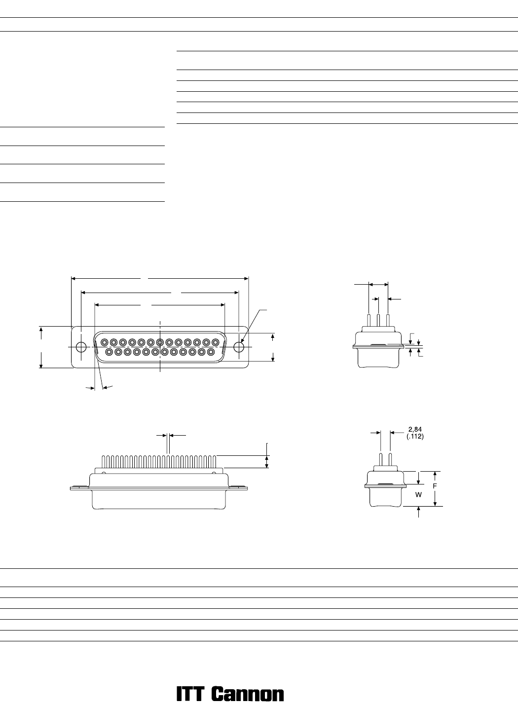
Dimensions
ABCDEFWWKKL
Shell Size ±0,38 (.015) ±0,13 (.005) ±0,13 (.005) ±0,13 (.005) ±0,38 (.015) ±0,25 (.010) ±0,368 (.0145) ±0,41 (.016) ±0,317 (.0125) ±0,25 (.010) ±0,25 (.010)
DE 30,81 (1.213) 16,92 (.666) 24,99 (.984) 8,36 (.329) 12,55 (.494) 10,72 (.422) 6,693 (.2635) 1,206 (.0475) 0,76 (.030)
DA 39,14 (1.541) 25,25 (.994) 33,32 (1.312) 8,36 (.329) 12,55 (.494) 10,72 (.422) 6,693 (.2635) 1,206 (.0475) 0,76 (.030)
DB 53,04 (2.088) 38,96 (1.534) 47,04 (1.852) 8,36 (.329) 12,55 (.494) 10,82 (.426) 6,84 (.269) 1,52 (.060) 0,99 (.039)
DC 69,32 (2.729) 55,42 (2.182) 63,50 (2.500) 8,36 (.329) 12,55 (.494) 10,82 (.426) 6,84 (.269) 1,52 (.060) 0,99 (0.39)
DD 66,93 (2.635) 52,81 (2.079) 61,11 (2.406) 11,07 (.436) 15,37 (.605) 10,82 (.426) 6,84 (.269) 1,52 (.060) 0,99 (.039)
Engaging Face DD Configuration
A
B
C
10°
E
D
Ø 3,05
(.120)
X
Ø Y
2,84
(.112)
5,69
(.224)
L
K
PC Tail
Modifiers X W Y
M 4,01 ± 0,69
(.158 ± .027)
0,76 ± 0,08
(.030 ± .003)
Z 4,65 ± 0,69
(.183 ± .027)
0,76 ± 0,08
(.030 ± .003)
OL3 4,20 ± 1,10
(.185 ± .043)
0,60 ± 0,08
(.023 ± .003)
Dimensions are shown in mm (inch)
Dimensions subject to change
173
D Subminiature Space/High Reliability
Straight PC Tail
Receptacle
Reader’s Resource
ɀ For contact cavity arrangements,
see page 224.
ɀ For P.C. hole patterns, see page 275.
ɀ For panel cutouts, see page 221.
ɀ For hardware views (Standard), see page 226.
Part Numbers
Shell Size Layout Through Hole
Dual
Float Mount
DE 9 DEM9SOL3NM* DEMY9SOL3NM*
DA 15 DAM15SOL3NM* DAMY15SOL3NM*
DB 25 DBM25SOL3NM* DBMY25SOL3NM*
DC 37 DCM37SOL3NM* DCMY37SOL3NM*
DD 50 DDM50SOL3NM* DDMY50SOL3NM*
Notes: * For Residual Magnetism Level of 200 gamma, add B. Example: DEM9SOL3NMB
For shells with 50 microinches gold, add K52. Example: DEM9SOL3NMK52
For alternate PC tail modifiers (see tabulation), replace OL3 with M or Z. Example: DEM9SZNM
PC Tail
Modifiers X W Y
M 4,01 ± 0,69
(.158 ± .027)
0,76 ± 0,08
(.030 ± .003)
Z 4,65 ± 0,69
(.183 ± .027)
0,76 ± 0,08
(.030 ± .003)
OL3 4,20 ± 1,10
(.185 ± .043)
0,60 ± 0,08
(.023 ± .003)
Dimensions
ABCDEFWKL
Shell Size ±0,38 (.015) ±0,13 (.005) ±0,13 (.005) ±0,13 (.005) ±0,38 (.015) ±0,25 (.010) ±0,38 (.015) ±0,318 (.0125) ±0,25 (.010)
DE 30,81 (1.213) 16,33 (.643) 24,99 (.984) 7,90 (.311) 12,55 (.494) 10,90 (.429) 6,94 (.273) 1,206 (.0475) 0,76 (.030)
DA 39,14 (1.541) 24,66 (.971) 33,32 (1.312) 7,90 (.311) 12,55 (.494) 10,90 (.429) 6,94 (.273) 1,206 (.0475) 0,76 (.030)
DB 53,04 (2.088) 38,38 (1.511) 47,04 (1.852) 7,90 (.311) 12,55 (.494) 10,90 (.429) 6,94 (.273) 1,206 (.0475) 0,76 (.030)
DC 69,32 (2.729) 54,84 (2.159) 63,50 (2.500) 7,90 (.311) 12,55 (.494) 10,90 (.429) 6,94 (.273) 1,206 (.0475) 0,76 (.030)
DD 66,93 (2.635) 52,42 (2.064) 61,11 (2.406) 10,74 (.423) 15,37 (.605) 10,90 (.429) 6,94 (.273) 1,206 (.0475) 0,76 (.030)
Engaging Face
DD Configuration
A
B
C
10
°
E
D
Ø 3,05
(.120)
Ø Y
X
2,84
(.112)
5,69
(.224)
L
K
2,84
(.112)
F
W
PREVIOUS5152535455565758596061626364NEXT