Dimensions are shown in mm (inch)
Dimensions subject to change
167
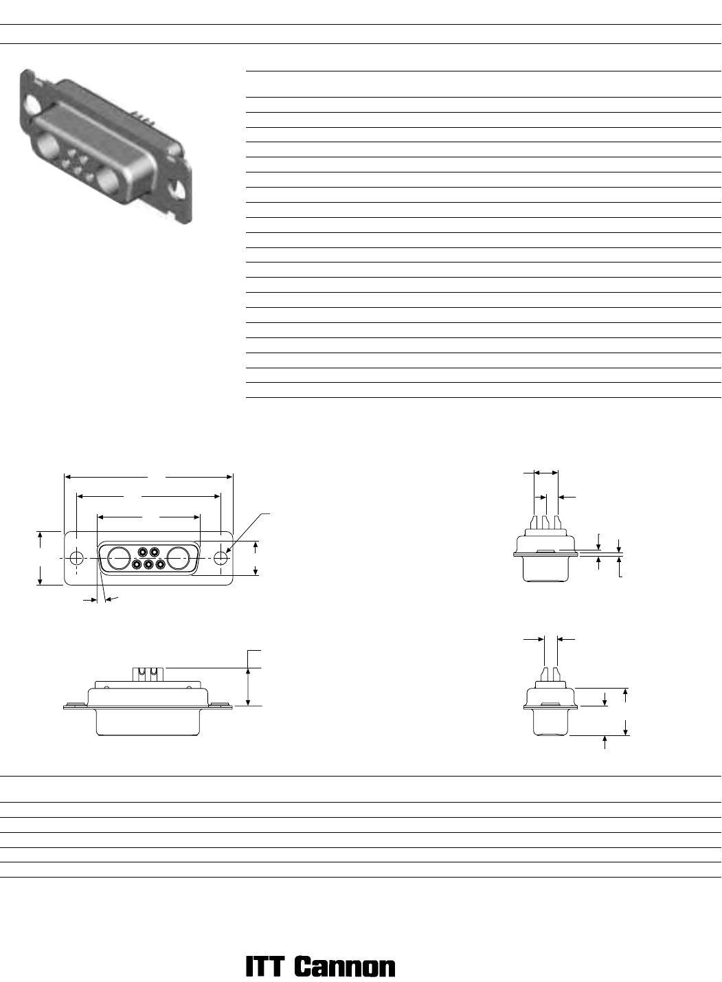
D Subminiature Military/High Reliability
Cable Solder Cup
Receptacle
Reader’s Resource
ɀ For contact cavity arrangements,
see page 223.
ɀ For panel cutouts, see page 221.
ɀ For hardware views (Standard), see page 226.
Part Numbers
Shell Size Layout Through Hole
Dual
Float Mount
Clinch Nut
#4-40 UNC
DE 5W1 DEMM5W1S DEMMY5W1S DEMME5W1S
DA 7W2 DAMM7W2S DAMMY7W2S DAMME7W2S
DA 11W1 DAMM11W1S DAMMY11W1S DAMME11W1S
DA 3W3 DAMM3W3S DAMMY3W3S DAMME3W3S
DA 3WK3ឮ DAMM3WK3S DAMMY3WK3S DAMME3WK3S
DB 5W5 DBMM5W5S DBMMY5W5S DBMME5W5S
DB 9W4 DBMM9W4S DBMMY9W4S DBMME9W4S
DB 13W3 DBMM13W3S DBMMY13W3S DBMME13W3S
DB 17W2 DBMM17W2S DBMMY17W2S DBMME17W2S
DB 21W1 DBMM21W1S DBMMY21W1S DBMME21W1S
DC 8W8 DCMM8W8S DCMMY8W8S DCMME8W8S
DC 13W6 DCMM13W6S DCMMY13W6S DCMME13W6S
DC 17W5 DCMM17W5S DCMMY17W5S DCMME17W5S
DC 21WA4 DCMM21WA4S DCMMY21WA4S DCMME21WA4S
DC 25W3 DCMM25W3S DCMMY25W3S DCMME25W3S
DC 27W2 DCMM27W2S DCMMY27W2S DCMME27W2S
DD 24W7 DCMM24W7S DCMMY24W7S DCMME24W7S
DD 36W4 DCMM36W4S DCMMY36W4S DCMME36W4S
DD 43W2 DCMM43W2S DCMMY43W2S DCMME43W2S
DD 47W1 DCMM47W1S DCMMY47W1S DCMME47W1S
Note: ឮ Keyed.
Dimensions
Shell Size
A
±0,38 (.015)
B
±0,13 (.005)
C
±0,13 (.005)
D
±0,13 (.005)
E
±0,38 (.015)
F
±0,25 (.010)
W
±0,38 (.015)
K
±0,318 (.0125)
L
±0,25 (.010)
DE 30,81 (1.123) 16,33 (.643) 24,99 (.984) 7,90 (.311) 12,55 (.494) 10,90 (.429) 6,94 (.273) 1,206 (.0475) 0,76 (.030)
DA 39,14 (1.541) 24,66 (.971) 33,32 (1.312) 7,90 (.311) 12,55 (.494) 10,90 (.429) 6,94 (.273) 1,206 (.0475) 0,76 (.030)
DB 53,04 (2.088) 38,38 (1.511) 47,04 (1.852) 7,90 (.311) 12,55 (.494) 10,90 (.429) 6,94 (.273) 1,206 (.0475) 0,76 (.030)
DC 69,32 (2.729) 54,84 (2.159) 63,50 (2.500) 7,90 (.311) 12,55 (.494) 10,90 (.429) 6,94 (.273) 1,206 (.0475) 0,76 (.030)
DD 66,93 (2.635) 52,42 (2.064) 61,11 (2.406) 10,74 (.423) 15,37 (.605) 10,90 (.429) 6,94 (.273) 1,206 (.0475) 0,76 (.030)
Engaging Face DD Configuration
A
C
B
E
D
Ø 3,05
(.120)
10
°
9,91 (.390)
MAX
K
L
5,69
(.224)
2,84
(.112)
2,84 (.112)
F
W


