Dimensions are shown in mm (inch)
Dimensions subject to change
132
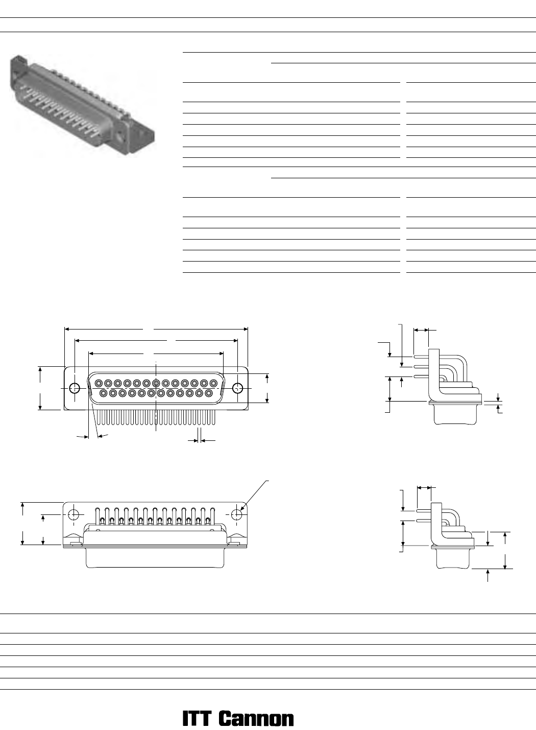
D Subminiature Military/High Reliability
90° PC Tail with Plastic Bracket
Part Numbers
Military Part Numbers
X Y X Y
0,76 (.030) 1,02 (.040)
Shell XXXXXX
Size Layout 3,23 (.127) 4,01 (.158) 4,65 (.183) 3,23 (.127) 4,01 (.158) 4,65 (.183)
DE 9 DEMM9PD DEMM9PL DEMM9PS DEMM9PA DEMM9PG DEMM9PW
DA 15 DAMM15PD DAMM15PL DAMM15PS DAMM15PA DAMM15PG DAMM15PW
DB 25 DBMM25PD DBMM25PL DBMM25PS DBMM25PA DBMM25PG DBMM25PW
DC 37 DCMM37PD DCMM37PL DCMM37PS DCMM37PA DCMM37PG DCMM37PW
DD 50 DDMM50PD DDMM50PL DDMM50PS DDMM50PA DDMM50PG DDMM50PW
Commercial Part Numbers
X Y X Y
0,76 (.030) 1,02 (.040)
Shell XXXXXX
Size Layout 3,23 (.127) 4,01 (.158) 4,65 (.183) 3,23 (.127) 4,01 (.158) 4,65 (.183)
DE 9 DEM9PD DEM9PL DEM9PS DEM9PA DEM9PG DEM9PW
DA 15 DAM15PD DAM15PL DAM15PS DAM15PA DAM15PG DAM15PW
DB 25 DBM25PD DBM25PL DBM25PS DBM25PA DBM25PG DBM25PW
DC 37 DCM37PD DCM37PL DCM37PS DCM37PA DCM37PG DCM37PW
DD 50 DDM50PD DDM50PL DDM50PS DDM50PA DDM50PG DDM50PW
2,84
(.112)
7,18 ± 0,25
(.283 ± .010)
5,68
(.224)
X ± 0,69 (.027)
L
A
C
B
ED
Ø Y
10°
M
N
Ø 3,05
(.120)
Plug
Engaging Face
DD Configuration
2,84
(.112)
F
W
7,18 ± 0,25
(.283 ± .010)
X ± 0,69 (.027)
Reader’s Resource
ɀ For contact cavity arrangements,
see page 224.
ɀ For P.C. hole patterns, see page 272.
ɀ For panel cutouts, see page 221.
Dimensions
Shell Size
A
±0,38 (.015)
B
±0,13 (.005)
C
±0,13 (.005)
D
±0,13 (.005)
E
±0,38 (.015)
F
±0,25 (.010)
W
±0,368 (.0145)
W
±0,41 (.016)
L
±0,25 (.010)
M
±0,25 (.010)
N
±0,13 (.005)
DE 30,81 (1.213) 16,92 (.666) 24,99 (.984) 8,36 (.329) 12,55 (.494) 10,72 (.422) 6,693 (.2635) — 0,76 (.030) 12,30 (.484) 8,64 (.340)
DA 39,14 (1.541) 25,25 (.994) 33,32 (1.312) 8,36 (.329) 12,55 (.494) 10,72 (.422) 6,693 (.2635) — 0,76 (.030) 12,30 (.484) 8,64 (.340)
DB 53,04 (2.088) 38,96 (1.534) 47,04 (1.852) 8,36 (.329) 12,55 (.494) 10,82 (.426) — 6,84 (.269) 0,99 (.039) 12,30 (.484) 8,64 (.340)
DC 69,32 (2.729) 55,42 (2.182) 63,50 (2.500) 8,36 (.329) 12,55 (.494) 10,82 (.426) — 6,84 (.269) 0,99 (.039) 12,30 (.484) 8,64 (.340)
DD 66,93 (2.635) 52,81 (2.079) 61,11 (2.406) 11,07 (.436) 15,37 (.605) 10,82 (.426) — 6,84 (.269) 0,99 (.039) 15,09 (.594) 10,04 (.395)


