Freelance Electronics Components Distributor
Closed Dec 25th-26th
800-300-1968
We Stock Hard to Find Parts

DE121073-54

Part # DE121073-54
Description Connector Accessories CopperAlloy EMI Shielded Backshell
Category BACKSHELL
Availability In Stock
Qty 2
Qty Price
1 + $8.71492
Manufacturer Available Qty
ITT CANNON
  • Shipping Freelance Stock: 2
    Ships Immediately


Technical Document


DISCLAIMER: The information provided herein is solely for informational purposes. Customers must be aware of the suitability of this product for their application, and consider that variable factors such as Manufacturer, Product Category, Date Codes, Pictures and Descriptions may differ from available inventory.

Dimensions are shown in mm (inch)
Dimensions subject to change
129
D Subminiature Filter D
D*JT Combo — High Power Solder Cup
Receptacle
Reader’s Resource
ɀ For contact cavity arrangements,
see page 223.
ɀ For panel cutouts, see page 221.
ɀ For hardware views (European),
see page 227.
Part Numbers
Filter
Capacitance Through Hole
Clinch Nut
#4-40 UNC
Clinch Nut
M3
1000 pF DAJT3W3S1 DAJTE3W3S1 DAJTX3W3S1
1500 pF DAJT3W3S6 DAJTE3W3S6 DAJTX3W3S6
5000 pF DAJT3W3S5 DAJTE3W3S5 DAJTX3W3S5
47000 pF DAJT3W3S9 DAJTE3W3S9 DAJTX3W3S9
Note: For performance class 1 add -A190. Example: DAJT3W3S6-A190
Part Numbers — Keyed Configuration
Filter
Capacitance Through Hole
Clinch Nut
#4-40 UNC
Clinch Nut
M3
1000 pF DAJT3WK3S1 DAJTE3WK3S1 DAJTX3WK3S1
1500 pF DAJT3WK3S6 DAJTE3WK3S6 DAJTX3WK3S6
5000 pF DAJT3WK3S5 DAJTE3WK3S5 DAJTX3WK3S5
47000 pF DAJT3WK3S9 DAJTE3WK3S9 DAJTX3WK3S9
Note: For performance class 1 add -A190. Example: DAJT3WK3S6-A190
For electrical data, see page 107.
Dimensions
Shell Size
A
±0,38 (.015)
B
±0,13 (.005)
C
±0,13 (.005)
D
±0,13 (.005)
E
±0,38 (.015)
F
±0,25 (.010)
W
±0,38 (.015)
L
±0,25 (.010)
DA 39,14 (1.541) 24,66 (.971) 33,32 (1.312) 7,90 (.311) 12,55 (.494) 10,90 (.429) 6,94 (.273) 0,76 (.030)
Engaging Face
L
W
F
Keyed Configuration
Engaging Face
A1
A3
E
C
A
B
D
10°
Ø 3,05 (.120)
Ø 3,63 (.143)
15,90 ± 0,50
(.626 ± .011)
A1
A3
E
C
A
B
D
10°
Ø 3,05 (.120)
Dimensions are shown in mm (inch)
Dimensions subject to change
130
D Subminiature Military/High Reliability
Selection Index Page
Military/High Reliability
An Introduction .......................................................130
Standard Layout
90° PC Tail with Plastic Bracket .........................................132
90° PC Tail.........................................................134
Straight PC Tail .....................................................136
Wrap Post Connector .................................................138
Solder Cup Connector ................................................140
MIL-C-24308 Cross Reference ...........................................142
MIL-C-39028 Crimp Contacts ............................................143
HE501/D*M Cross Reference ............................................144
MIL-24308 Test Data ..................................................145
Combo D
PCB Connectors with Coaxial 75 Ohm Contacts (50 Ohm Option)
Coaxial 90° (Sizes DE-DC) .............................................146
Coaxial 90° (Size DD).................................................148
Coaxial Straight (Sizes DE-DC) ..........................................150
Coaxial Straight (Size DD)..............................................152
Combo D
PCB Connectors with High Power Contacts
40 A High Power 90° (Sizes DE-DC)......................................154
40 A High Power 90° (Size DD) .........................................156
40 A High Power Straight (Sizes DE-DC)...................................158
40 A High Power Straight (Size DD) ......................................160
Combo D
PCB Connectors with High Voltage Contacts
High Voltage Straight (Sizes DE-DC) ......................................162
High Voltage Straight (Size DD)..........................................164
Combo D
PCB Connectors with (Size 20) Signal Contacts Only
Cable Solder Cup (Sizes DE-DD).........................................166
Dimensions are shown in mm (inch)
Dimensions subject to change
131
ytilibaileR hgiH/yratiliMerutainimbuS D
I
TT Cannon Military/High Reliability D
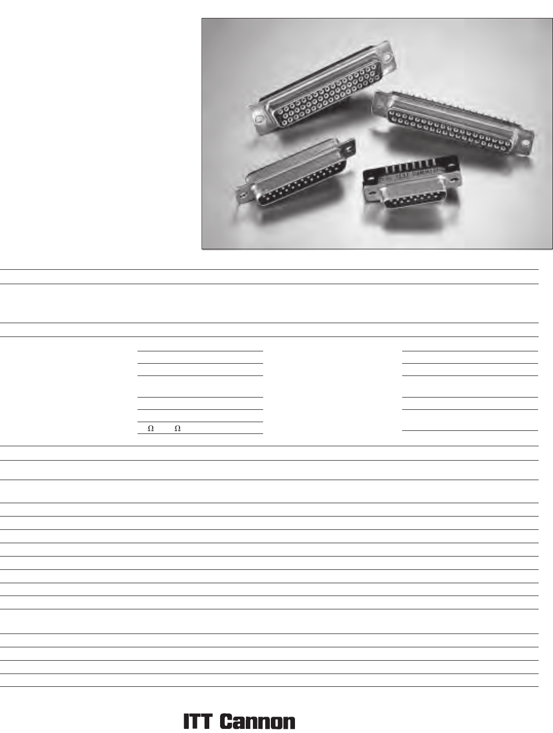
Subminiature connectors are used in many
application s , includi n g aeros p ace ,
transportation, communication systems,
information systems and test equipment. Being the
inventor of the D Subminiature connector,
ITT Cannon is able to use its extensive design
expertise and high quality manufacturing
processes to insure the optimum performance and
reliability.
The D Subminiature connectors with xed
contacts in solder cup, straight and 90
° PC contact
terminations are qualied to MIL-C-24308 (see
cross reference, pages 142-143). These high-
reliability D Subminiature connectors are the nest
quality connectors available at the most
competitive prices in the market.
Applications:
Aerospace
Transportation
Communication Systems
Information Systems
Test Equipment
Product Features
Materials and Finishes
tnemtaerT/hsiniFlairetaMnoitpircseD
cniZ revo etamorhC wolleYleetSllehS
(Cadmium available upon request; order code -A101)
enoNneerG :roloC ,0-V49 LU ,retseyloProtalusnI
Contacts (Military) Copper Alloy
Contacts (Commercial) Copper Alloy
Dual Float Mount Hardware Stainless Steel Passivated
Clinch Nut Hardware Stainless Steel with plastic insert Passivated
leetS ffodnatS
Plastic Bracket Thermoplastic, UL 94V-0 None
)dehcatta era skcoldraob fi niT( cniZleetStekcarB lateM
Coaxial/High Power/High Voltage Contact Assemblies
Contacts and Outer Shells Copper Alloy Gold over Nickel
Ring, Retaining Copper Alloy Nickel
enoNnolfeT)ylnO laixaoC( rotalusnI
Insulator (High Voltage Only) Thermoplastic None
Specications
Suitable for a variety of cable and printed
circuit board options
Solder cup version accommodates wire size
20 AWG maximum
Temperature Rating 55°C to 125°C
Signal Contact Current Rating 7.5 A current capacity
Signal Contact Resistance 55 millivolt max. at 7.5 test current
Signal Contact
Dielectric Withstanding Voltage 1250 VAC at Sea Level
Coaxial Current Rating 5 A
Coaxial Dielectric Withstanding Voltage 1000 VAC at Sea Level
Coaxial Impedance 75 or 50
Coaxial VSWR Less than 1.30 + .03F for F up to 500 MHz
Coaxial Insertion Loss .3dB loss at 500 MHz
High Power Current Rating Up to 40 A
High Power
Dielectric Withstanding Voltage 1000 VAC at Sea Level
High Voltage Current Rating 5 A
High Voltage Contact
Dielectric Withstanding Voltage 2800 V at Sea Level
5 A standard current rating
Clinch Nut and Float Mount Options
Trivalent Chromate over Zinc
50 microinches of Gold over Nickel in mating area, Gold over Nickel on balance
Gold over Nickel on mating area, Tin on balance
PREVIOUS3738394041424344454647484950NEXT