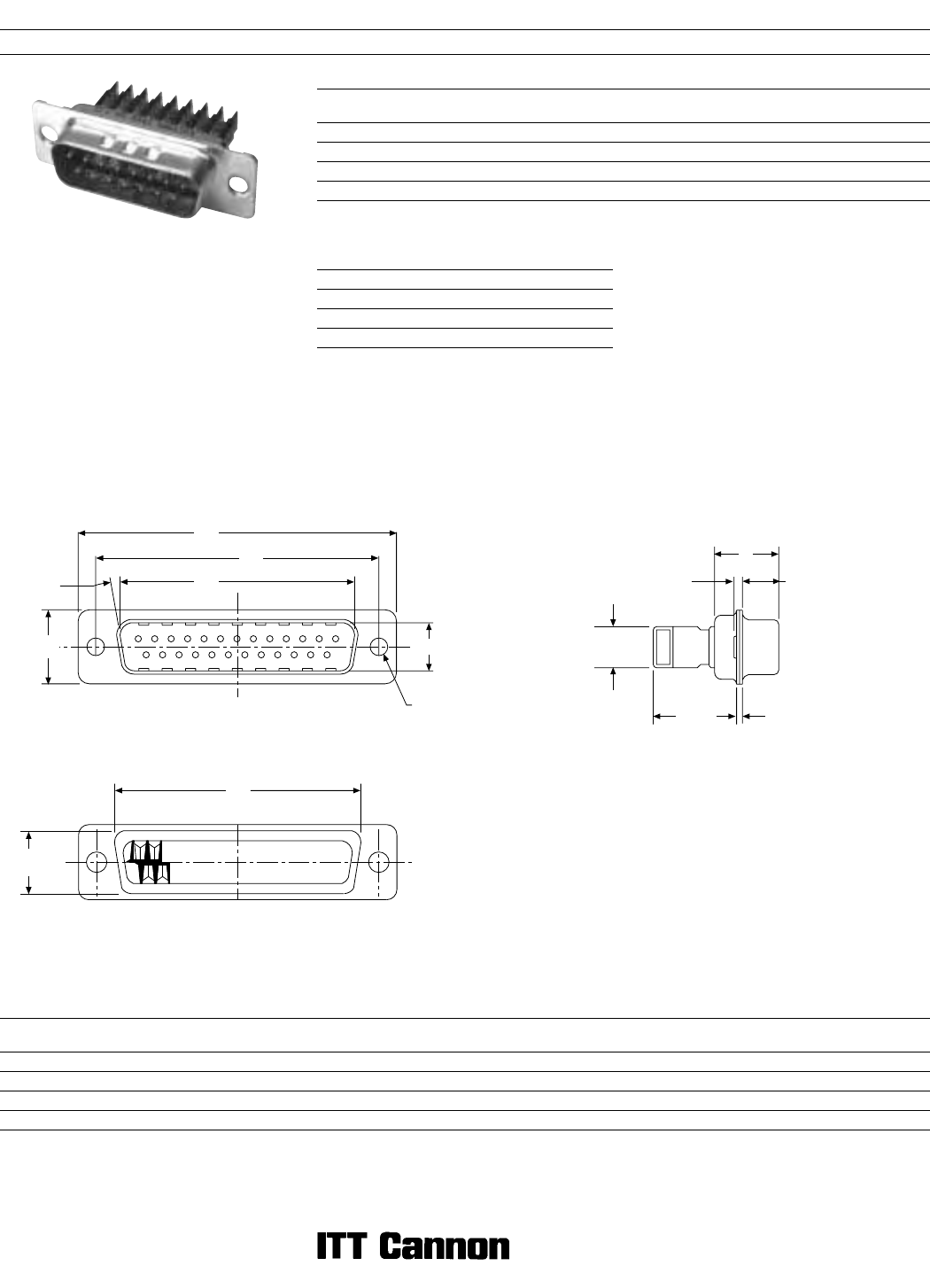
Dimensions are shown in mm (inch)
Dimensions subject to change
38
D Subminiature D*W
Discrete Wire IDC
Part Numbers
Shell Size Layout Through Hole
Clinch Nut
#4-40 UNC
Through Hole
& Shield Can Kit
Clinch Nut #4-40 UNC
& Shield Can Kit
DE 9 DEW9P* DEWE9P* DEW9P*G DEWE9P*G
DA 15 DAW15P* DAWE15P* DAW15P*G DAWE15P*G
DB 25 DBW25P* DBWE25P* DBW25P*G DBWE25P*G
DC 37 DCW37P* DCWE37P* DCW37P*G DCWE37P*G
Note: *Insert contact type. Example: DEW9P1.
For contacts with 0,76 Ȗm gold add -A176. Example: DEW9P1-A176.
For shield can kit, see page 40.
Contact Types* Wire Accommodation
1 28 AWG/30 AWG
2 22 AWG/26 AWG
3 20 AWG/22 AWG
For more information, see pages 40-41.
Dimensions
Shell Size Layout
A
±0,38 (.015)
B
±0,12 (.005)
C
±0,12 (.005)
D
±0,13 (.005)
E
±0,38 (.015)
F
±0,25 (.010)
G
max.
H
±0,25 (.010)
J
±0,25 (.010)
L
±0,25 (.010)
DEW 9 30,81 (1.213) 16,91 (.666) 24,99 (.984) 8,35 (.329) 12,55 (.494) 10,71 (.422) 6,05 (.238) 19,27 (.759) 10,71 (.422) 0,76 (.030)
DAW 15 39,14 (1.541) 25,54 (.994) 33,32 (1.312) 8,35 (.329) 12,55 (.494) 10,71 (.422) 6,05 (.238) 27,50 (1.083) 10,71 (.422) 0,76 (.030)
DBW 25 53,03 (2.048) 38,96 (1.534) 47,04 (1.852) 8,35 (.329) 12,55 (.494) 10,82 (.426) 5,99 (.236) 41,27 (1.625) 10,71 (.422) 0,99 (.039)
DCW 37 69,32 (2.729) 55,42 (2.182) 63,50 (2.500) 8,35 (.329) 12,55 (.494) 10,82 (.426) 5,99 (.236) 57,70 (2.272) 10,71 (.422) 0,99 (.039)
Plug
Engaging Face
Selection Guide
ɀ For Product Features, Specifications,
Materials and Finishes, see pages 30-31.
Reader’s Resource
ɀ For contact cavity arrangements,
see page 224.
ɀ For panel cutouts, see page 221.
ɀ For hardware views (European),
see page 227.
H
J
Rear Face
E
A
C
B
D
Ø 3,05 (.120)
10°
1
13
2514
F
1,33
(.052)
G MAX
7,00
(.276)
14,50
(.571)
L


