Philips Semiconductors Product specification
74F533,* 74F534Latch/flip-flop
1999 Jan 08
8
* Discontinued part. Please see the Discontinued Products List.
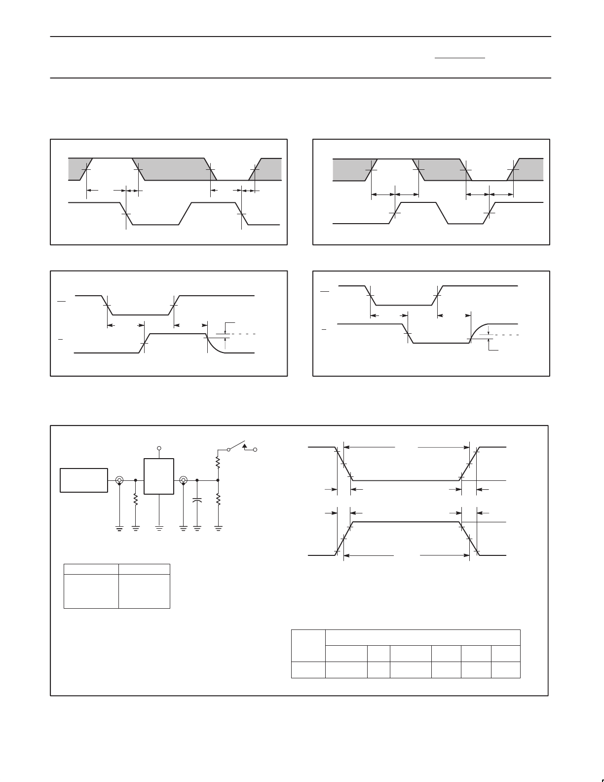
AC WAVEFORMS (Continued)
For all waveforms, V
M
= 1.5V
The shaded areas indicate when the input is permitted to change for predictable output performance.
E
Dn
V
M
V
M
V
M
V
M
V
M
V
M
t
s
(L)t
s
(H)
t
h
(L)t
h
(H)
SF00992
Waveform 4. Data Setup and Hold Times
t
h
(H)t
s
(H)
CP
SF00191
V
M
V
M
V
M
V
M
V
M
V
M
t
h
(L)t
s
(L)
Dn
Waveform 5. Data Setup and Hold Times
V
M
V
M
V
M
t
PHZ
t
PZH
OE
Qn
V
OH
-0.3V
0V
SF00994
Waveform 6. 3-State Output Enable Time to High Level
and Output Disable Time from High Level
V
M
V
M
V
M
t
PLZ
t
PZL
OE
Qn
V
OL
+0.3V
SF00995
Waveform 7. 3-State Output Enable Time to Low Level
and Output Disable Time from Low Level
TEST CIRCUIT AND WAVEFORM
t
w
90%
V
M
10%
90%
V
M
10%
90%
V
M
10%
90%
V
M
10%
NEGATIVE
PULSE
POSITIVE
PULSE
t
w
AMP (V)
0V
0V
t
THL
(
t
f
)
INPUT PULSE REQUIREMENTS
rep. rate
t
w
t
TLH
t
THL
1MHz 500ns
2.5ns 2.5ns
Input Pulse Definition
V
CC
family
74F
D.U.T.
PULSE
GENERATOR
R
L
C
L
R
T
V
IN
V
OUT
Test Circuit for 3-State Outputs
DEFINITIONS:
R
L
= Load resistor;
see AC electrical characteristics for value.
C
L
= Load capacitance includes jig and probe capacitance;
see AC electrical characteristics for value.
R
T
= Termination resistance should be equal to Z
OUT
of
pulse generators.
t
THL
(
t
f
)
t
TLH
(
t
r
)
t
TLH
(
t
r
)
AMP (V)
amplitude
3.0V
1.5V
V
M
R
L
7.0V
SF00777
TEST SWITCH
t
PLZ
closed
t
PZL
closed
All other open
SWITCH POSITION


